
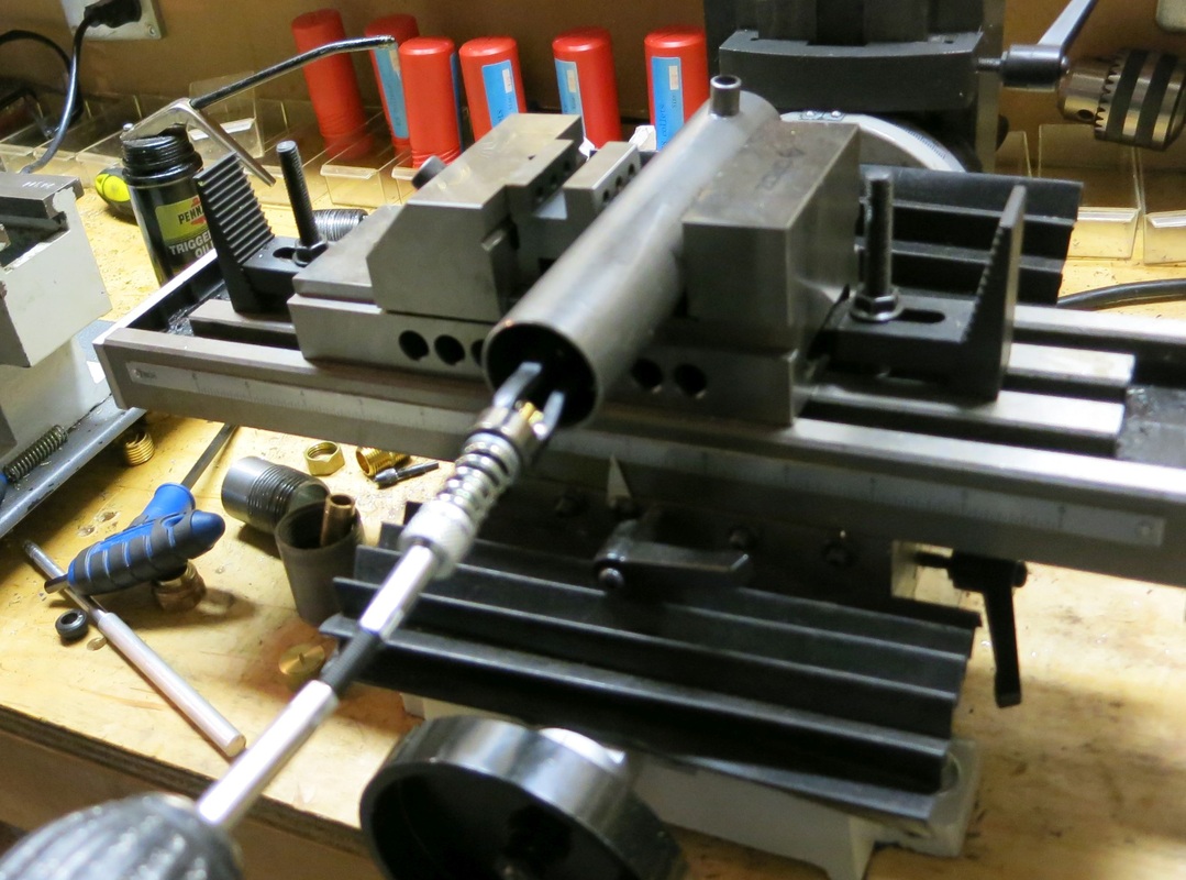
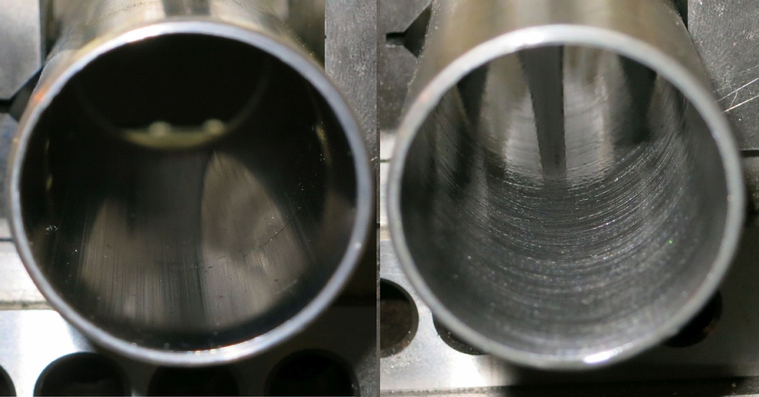
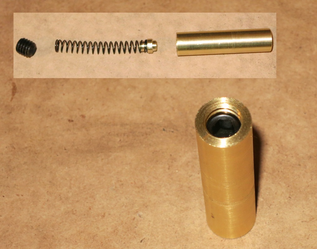
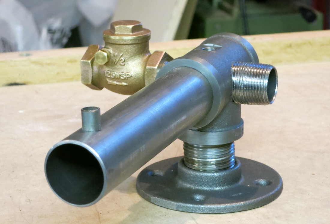
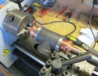
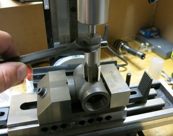
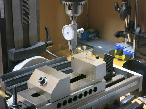
Today I received my centering indicator in the mail, so naturally I wanted to try it out. Today I worked on the exhaust valve. This involved many operations that I have never done before, but it seemed to work out in the end.
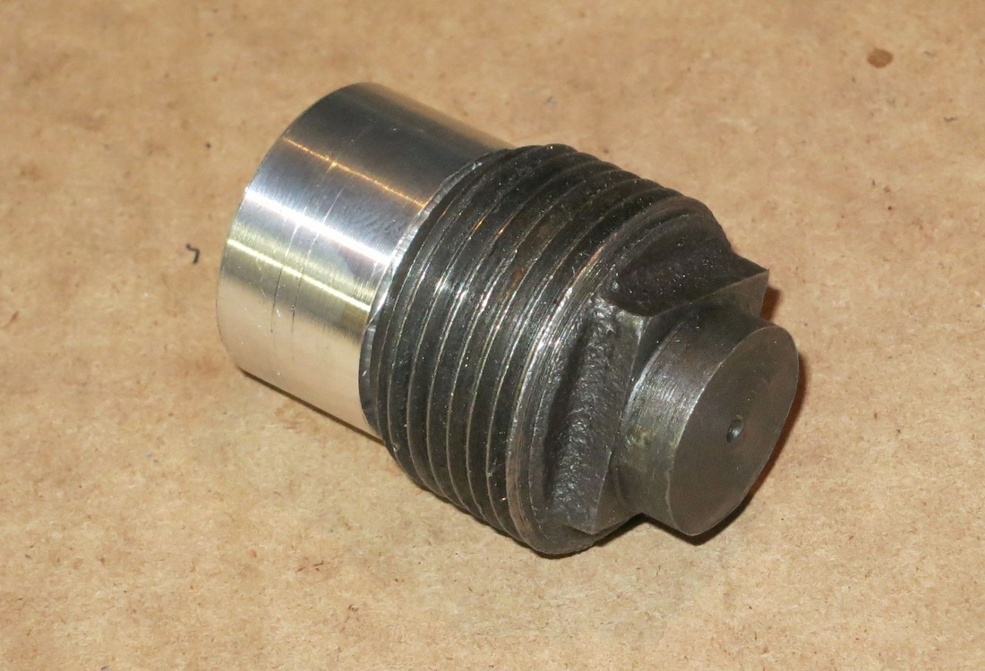
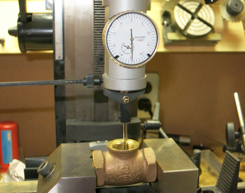 Center Indicator locating the center of this valve. | 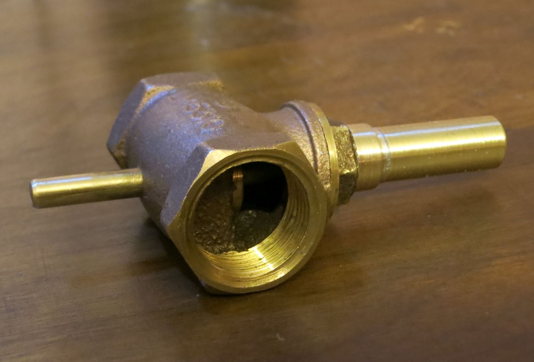 The finished exhaust valve. |

 RSS Feed
