Tonight I finally got the HF1E to run! Turned out the problem was that I did not have the timing advanced enough for it to work properly.
Here is a short video of it running. Enjoy.
Here is a short video of it running. Enjoy.

|
|
|
Tonight I finally got the HF1E to run! Turned out the problem was that I did not have the timing advanced enough for it to work properly. Here is a short video of it running. Enjoy.
0 Comments
Did a bit more work on the HF1E tonight. Raised the combustion chamber about a 1/16" so that the connecting rod is better centered in cylinder as it was scraping a bit on the top during part of the stroke. Then I removed the intake valve and filled the cap with lead. These two things didn't seem to help much. For some reason the engine doesn't ignite on every stroke, but every other stroke, or less. Maybe I have to play around more with the spark timing.
Discovered that I had a leak where the exhaust nipple enters the combustion chamber. I sealed that up with some Permatex thread sealer and tried again to start the engine. I did manage to get it to fire a few times, but the firing was intermittent, and I could not get it to fire often enough to sustain rotation. It seems also, that I was not completely successful sealing that leak. When combustion occurred, a stream of exhaust would spray from a pinhole leak at the threads. I will have to take this apart and try some JB Weld this weekend. Hopefully that works.
Leon Ridenour also suggested that I modify the oiler so that the gasoline droplets are no so large. One thing I did not do was modify it with a tapered tube as per his instructions. That is not going to be easy as it requires drilling with a very small drill (0.025"). This weekend my wife and I showed off the HF1E along with Heron's steam ball at the Toronto Mini Maker Faire. It is estimated that approximately 10,000 people visited the Faire. And it looked like it too. At times the space was packed with people. A fair number of them came and looked (and touched) the engine. I could not demonstrate it running because it was inside, but they got to turn the flywheel and watch the mechanism in action. It's a good thing too, as I have not yet quite got it going. This week I will work on that, but for now it was in good enough shape to show off. 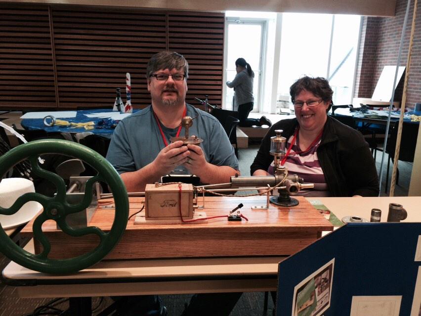 My wife and us at the Toronto Mini Maker Faire. 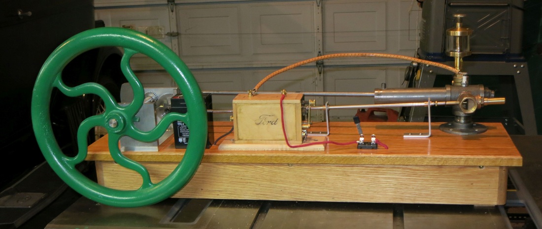 HF1e with new 18 pound flywheel installed. After a brief discussion with Leon Ridenour (the originator of the plans), I decided to get a heavier flywheel. Fortunately, my wife's uncle had an old post drill with a suitable flywheel. We got it off the beast and after painting it, I put it on the HF1e.
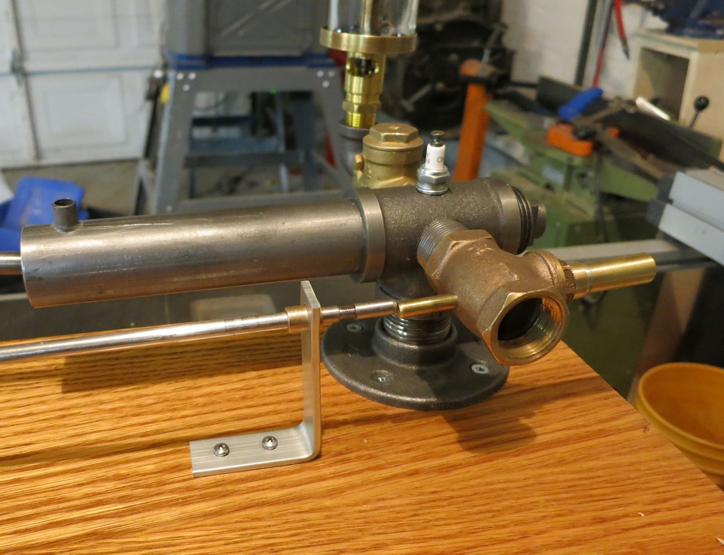
I also ordered a proper glass and gaskets for my oiler. Hopefully those arrive early next week. And hopefully, I can get the thing to run. :-) The other day I wired up the HF1E using a modified Model T coil with screw terminals and mounted on the base. I tried starting her on QuickStart the other day, but she did not fire, not even once. After some reading and troubleshooting, I determined that the problem was the exhaust valve. It seems that the valve guide was not allowing it to seat correctly. I drilled a larger hole in the base of it, and that seemed to help. No I can actually feel the compression when I turn it over. However, the plug at the end of the spring gets stuck occasionally and sometimes it still doesn't seat. Despite that, I managed to get a few bangs as I turned it over today, so I know that I am close. 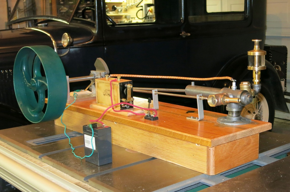 Today I finished up on the mechanical aspects of my replica of Henry Ford's first engine. The last things on my list were to install the valve lifter (tapper) and the piston ring. Now all that remains to to work on the electrical parts. 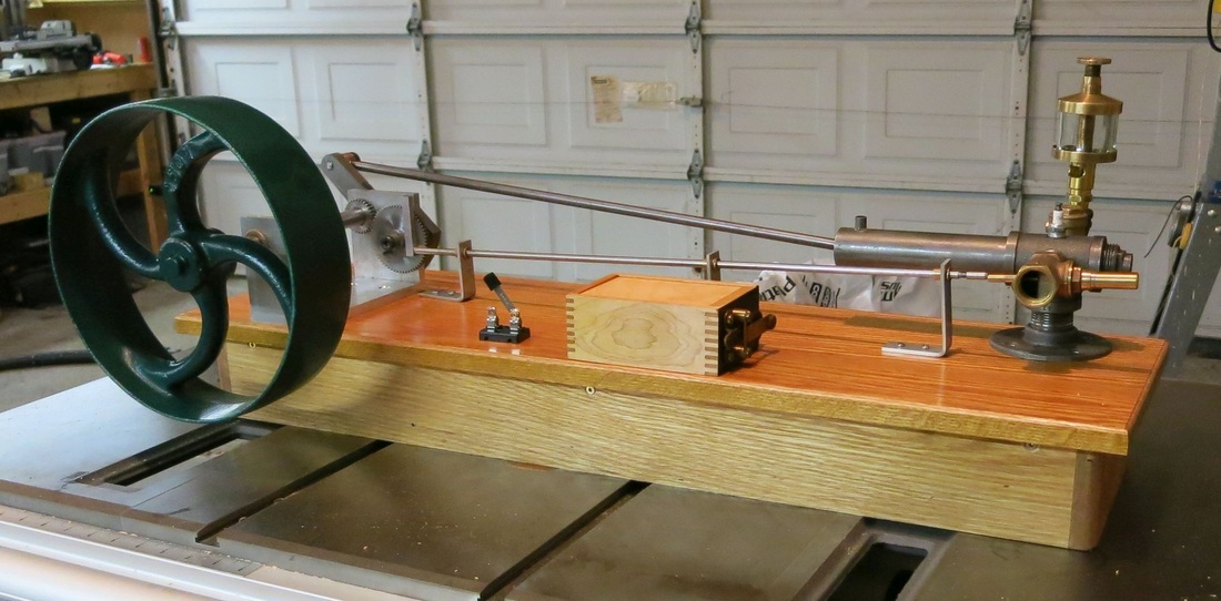 The engine as it looks today.
Today I finished up machining the piston. This was by far the most complicated and nerve wracking part to make. Lots of tricky operations and lots of opportunity for bozo moves! Any one of them would have set me back to starting with a new piece of round stock. A few times I got stumped for a bit while I figured out how to proceed. Fortunately I think I have succeeded on the first try. I am almost done. All that remains is to construct the valve actuator (tapper) and to finish work on the wooden base.
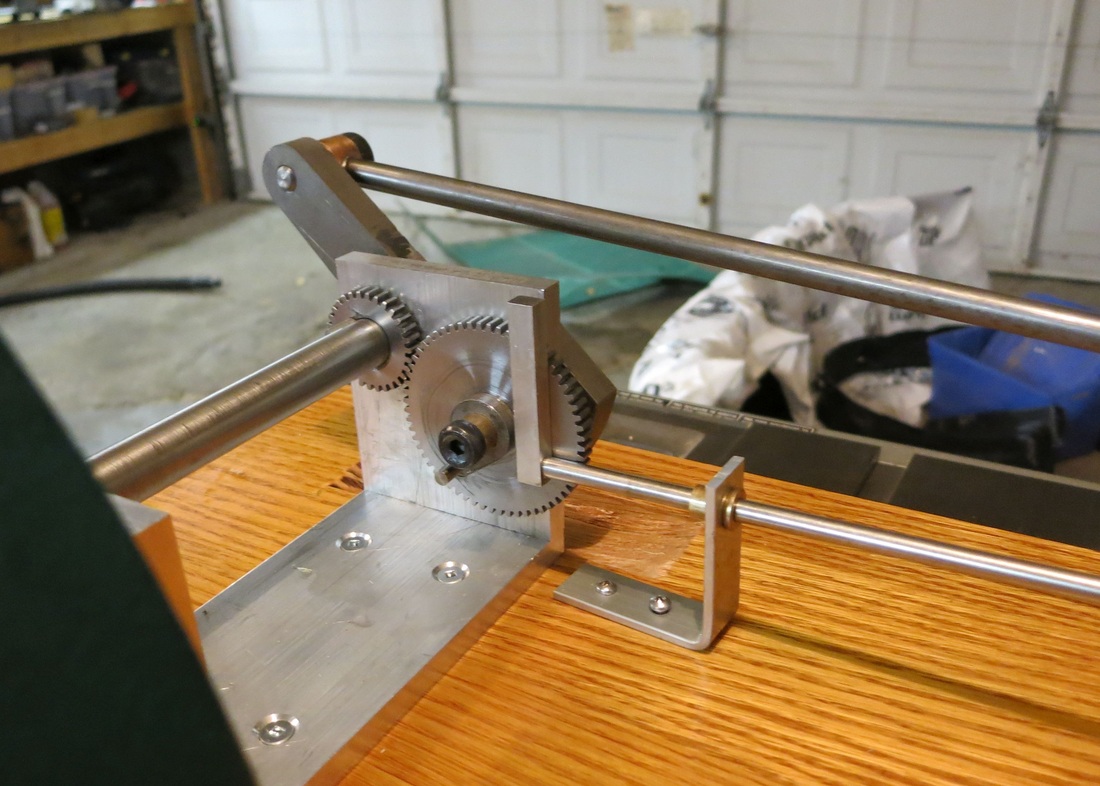
Last Friday, I took sent DXF files of the cam and the crank arm to a local firm that has a water-jet cutter. Today I got them back and they look fantastic. It cost me about $50 to do, but it saved me a lot of time I otherwise would have had to spend to make the parts by hand. The holes needed a bit of reaming and one of them needed to be threaded, but other than that, there was little I had to do to them. 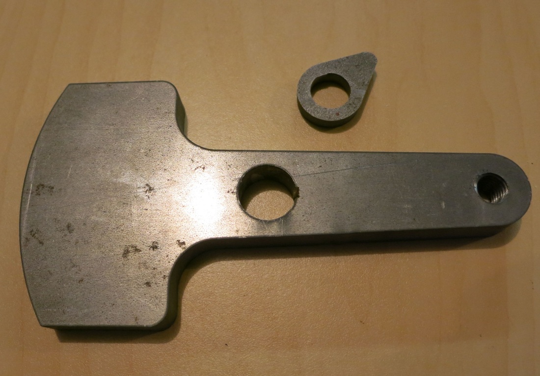 The crank arm and cam. Today I finished up work on the main bearing frame. I also cut the key-ways on the crank shaft for the 30 tooth gear and the crank handle. Then I pressed the shaft onto the flywheel. I had to make a shim to allow the flywheel to fit to the 5/8-inch diameter shaft. After that was done, I test assembled the components on a scrap piece of wood just to see what she would look like. See picture below. 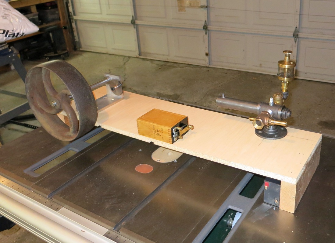 HF1E test assembled. |

AuthorCharles Baetsen holds a Bachelor and a Master's degree in Engineering Physics from McMaster University in Hamilton, Canada. Archives
February 2024
Categories
All
|

 RSS Feed
