Crankshaft shimmed, torqued and installed.
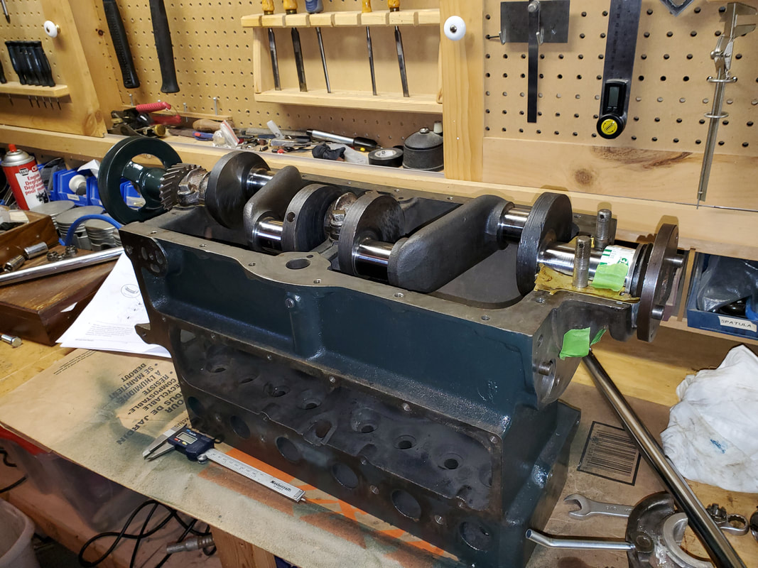 Crankshaft installed. | 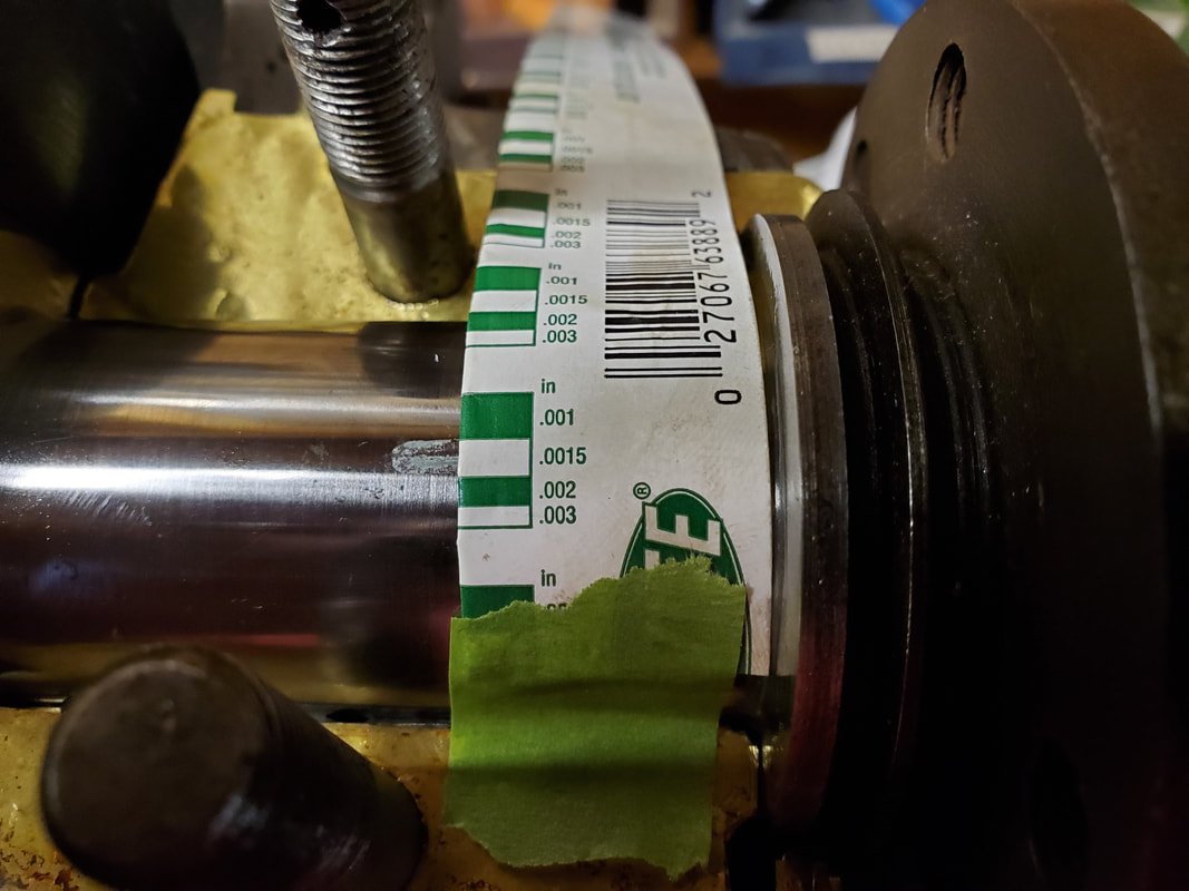 Plastigauge used to insure that the clearances are correct. |

|
|
|
Crankshaft shimmed, torqued and installed.
0 Comments
I managed to acquire this unique MIL business card with a small silicon chip embedded in it. At the time (~1970) this was quite a marvel. 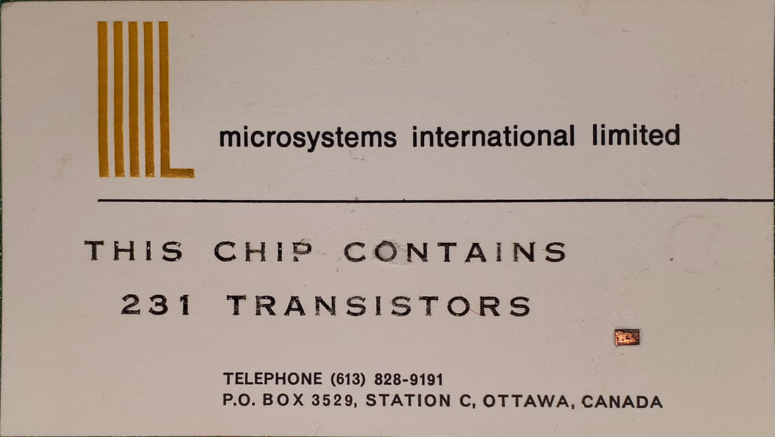 MIL Business Card from ~1970 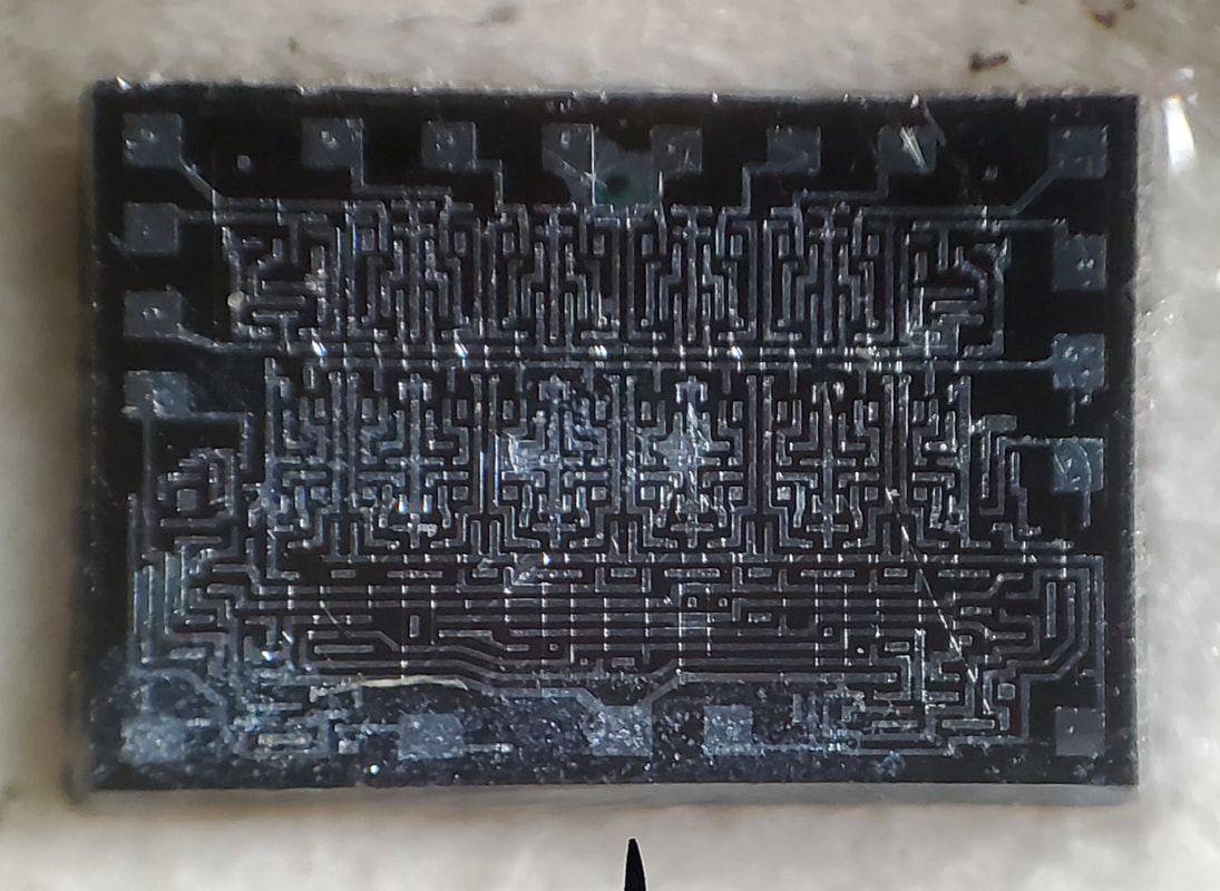 A closeup of the chip on the card. Unfortunately there are no markings to indicate what this was. With some help from Craig Andrews in the MIL Mod8 Facebook Group, he noted that CE2 had to be HIGH. I should have caught that when designing the board, but I assumed the 2101 was identical to the MIL 2113 except for the pin locations. Apparently on the MIL chip, CE2 was really !CE2, as that was one of the pins tied to ground. Once that was sorted out, I went to work lifting pin 17 on the RAM sockets and jumpered them to Vcc. Then the board worked 100%. This was a bit of a pain to do, however to fix this for the next run, is not a problem as I updated the Eagle drawings. 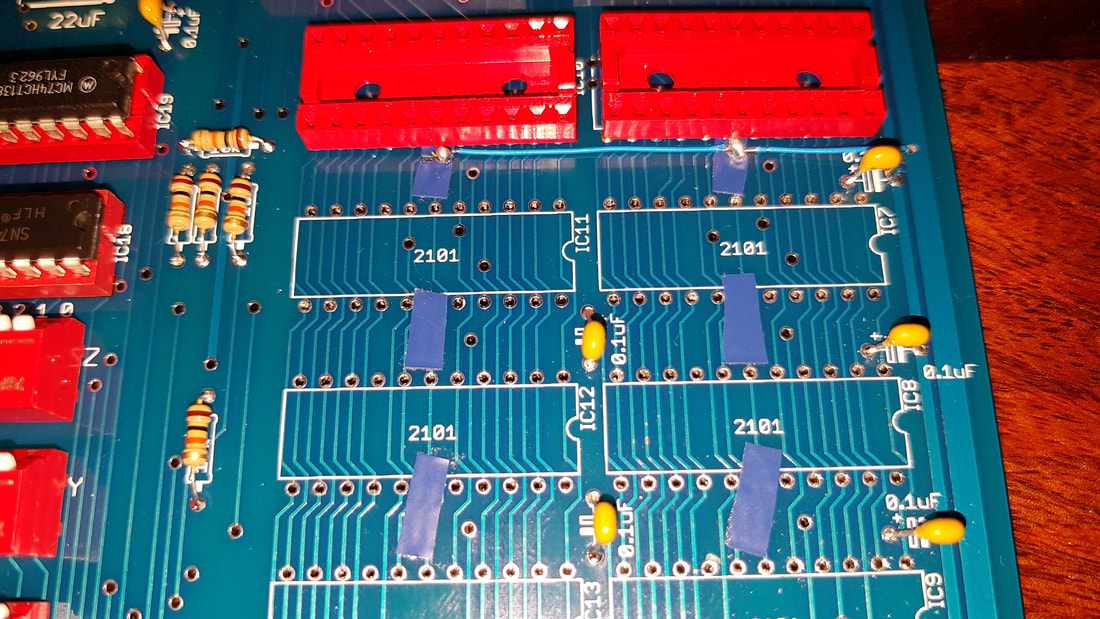 Pin 17 (CE2) lifted and jumpered to Vcc rail. Today I finished assembling my modified Mod8-6C board. Below you can see how it compares to the standard Mod8-6 input card. As you can see, the cassette interface circuit fits nicely into the top half of the board. I wonder if MiniMicroMart or anyone else used this solution in the past. It has one huge advantage in that you do not have to give up one of the I/O cards to use it. Next up is assembling the Mod8-9B and testing of both boards. Then board testing. 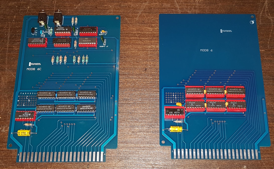 Mod8-6C vs Mod8-6 Today I finished up assembling the Mod8-9B board. Below is ab image of how it compares to the original MIL Mod8-9 board. So far it appears to work fine, except for the RAM portion. For some reason the 1 k block shows up as 377 (FF) when I read it. Writing data has no effect. Troubleshooting will have to wait until tomorrow. 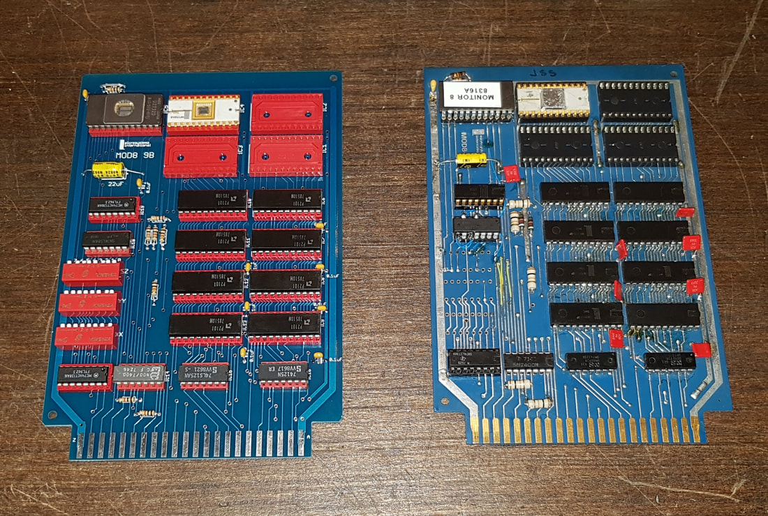 Two new Mod 8 prototype boards arrived have just arrived from China. One is a Mod8-9B (left) and the other (right) is a modified Mod8-6 board with cassette interface. I have been waiting to try out Robert Swartz's MIL cassette solution ever since I came across it. Mod8-9B The Mod8-9 was a combo board that had both RAM and ROM on it. The original board had a 2k 8316 ROM that contained a copy of Monitor 8 along with Robert Swartz's MIL cassette routine (located at 007000-007377), 1k of 1702A EPROM and 1k of MIL MF2113-2P RAM. Since the MIL RAM is nearly impossible to get a hold of, as is a pre-programmed 8316 with Monitor 8, I decided to use the more common 2716 EPROM and Intel 22-pin 2101 RAM instead. Unfortunately neither are a 100% pin compatible with the original chips, so the board had to be modified. No documentation was found for the MIL MF2113-2P RAM, so the pin-outs had to be reverse engineered from the original Mod8-9 board layout. Only two pins that could not be determined with certainty, these were CE2 and OD, however this did not matter for this application. The modified board was given the designation Mod8-9B to distinguish it from the original. Mod8-6C Robert Swartz's MIL cassette interface requires that the card be inserted in one of the two I/O slots in the Mod8-8 board. This would mean that you could not have one of the Mod8-6 or Mod8-7 boards in the system if you wanted to use the cassette to load or save data. Fortunately there is plenty of room on the Mod8-6 board for additional circuitry. It was not too difficult to add the cassette interface to that card. The result was what I call the Mod8-6C (C for Cassette). Over the next few weekends I hope to test these out and make sure they work before I order a production run for sale. 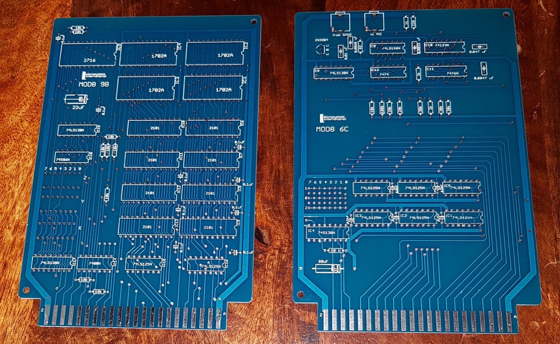 New prototype boards for the MIL Mod 8 |

AuthorCharles Baetsen holds a Bachelor and a Master's degree in Engineering Physics from McMaster University in Hamilton, Canada. Archives
February 2024
Categories
All
|
 RSS Feed
