
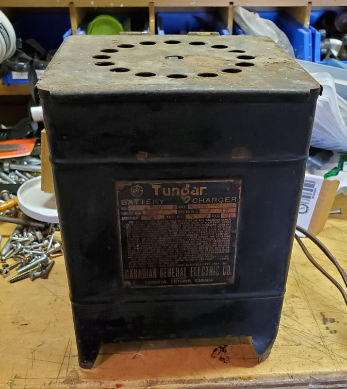
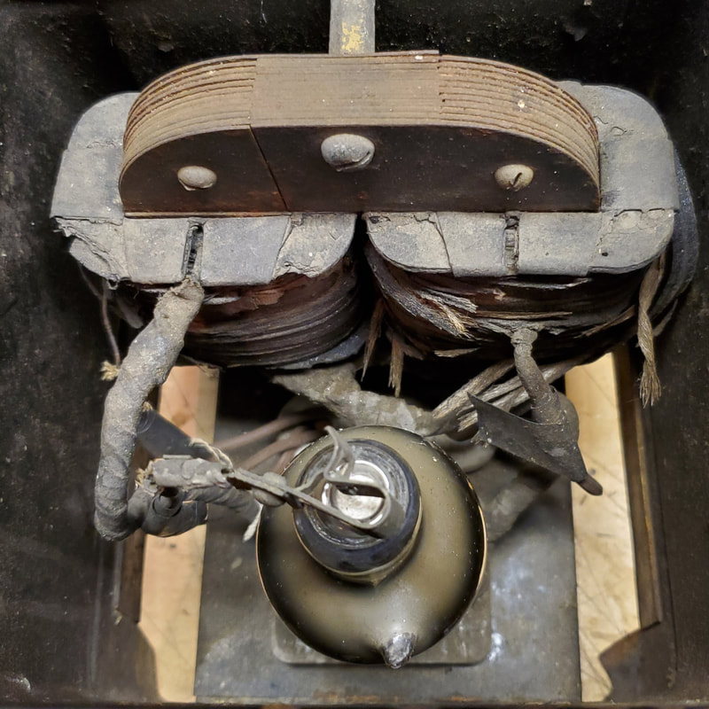
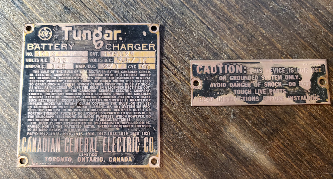
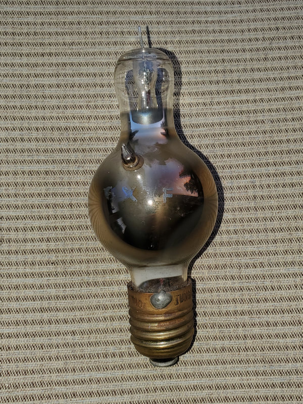
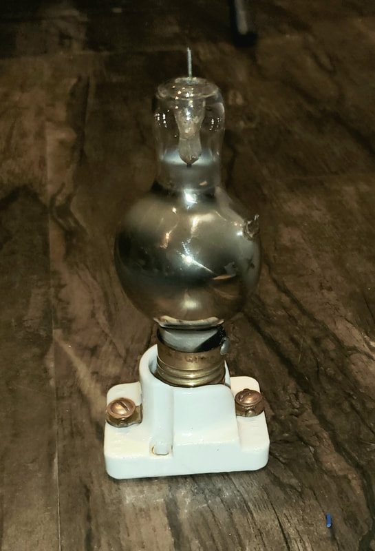
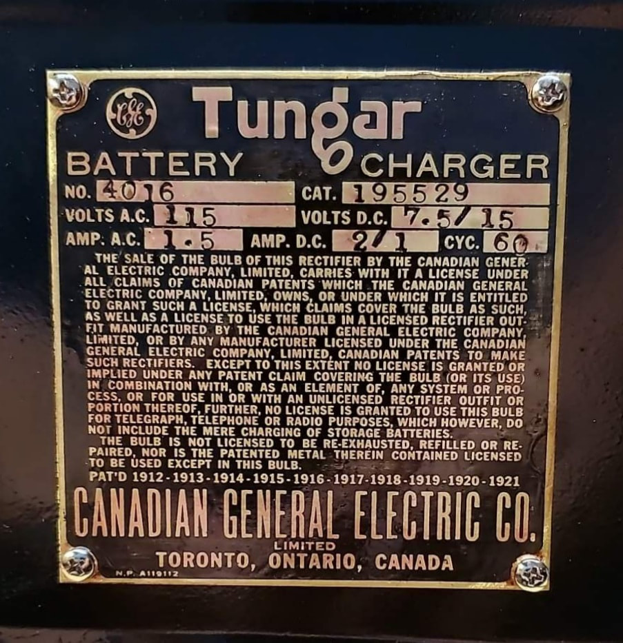
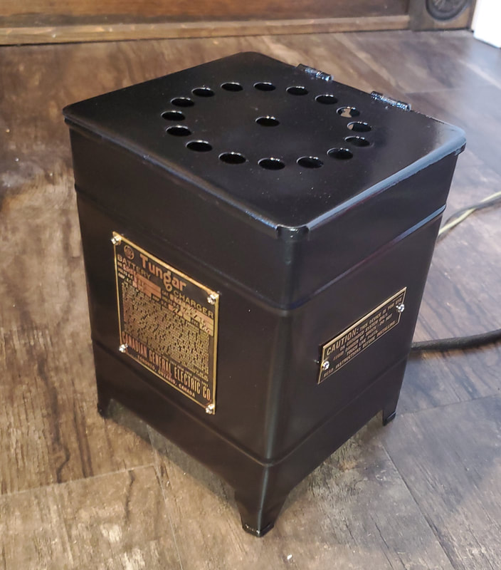
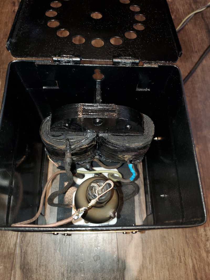
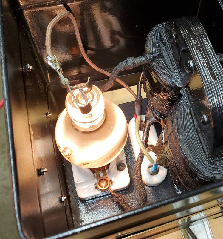
Restored this old 1920's Tungar 6V battery charger, which I picked up at a garage sale a few weeks ago. This will be a nice addition to my antique radio collection. It also can be used to charge my Model A battery up too. It uses a unique Tungar vacuum tube as a rectifier or diode.
|
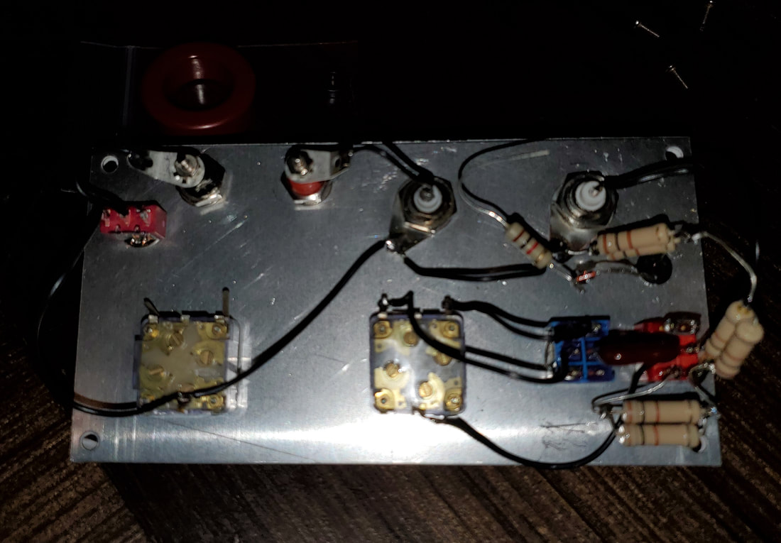
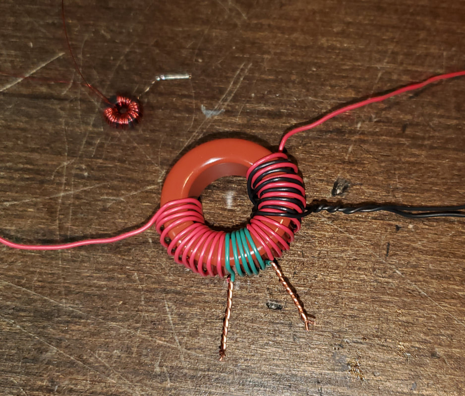
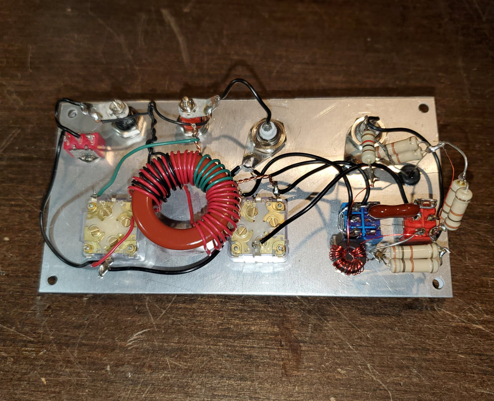
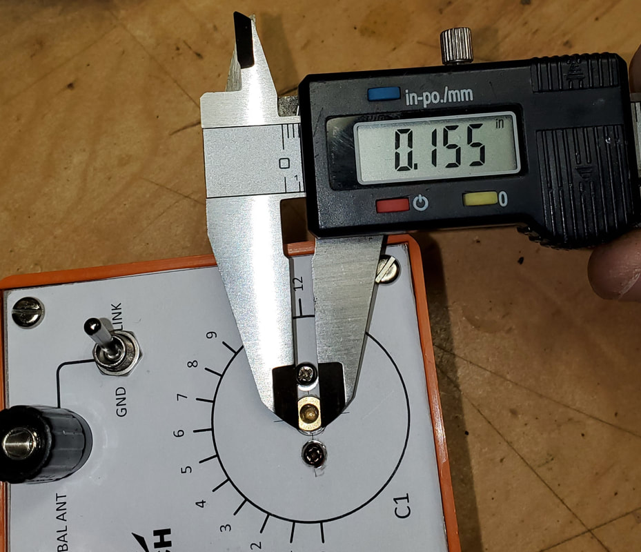
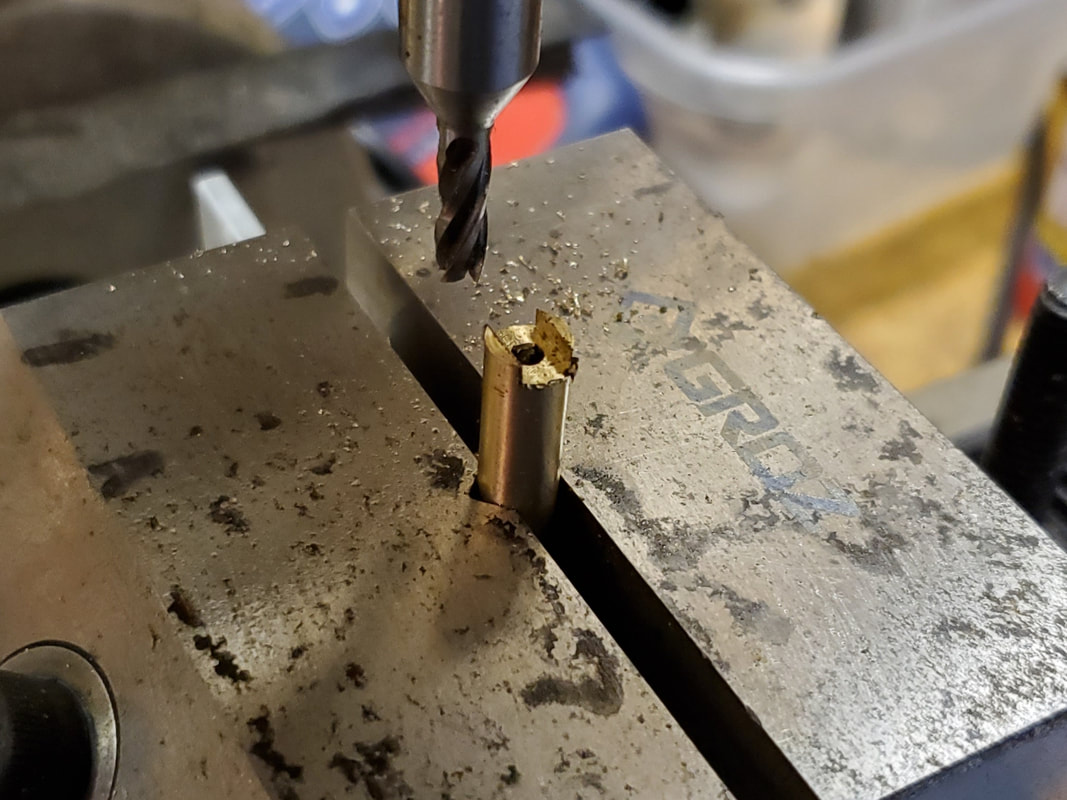
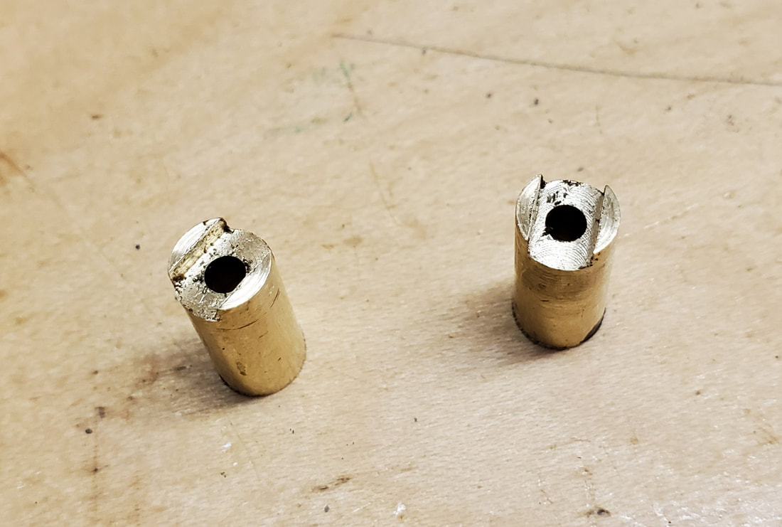
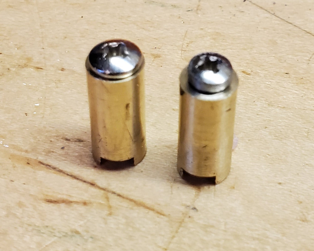
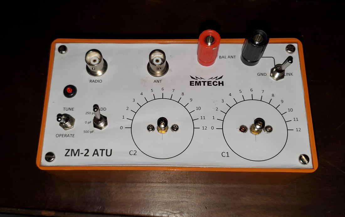
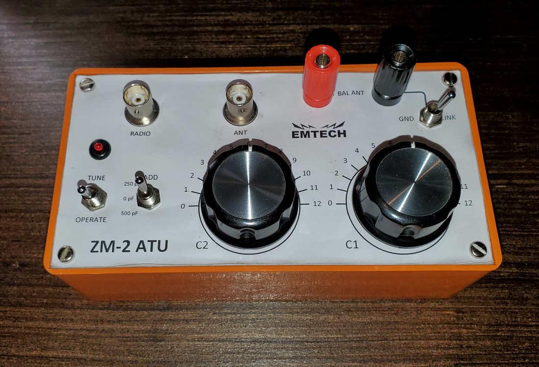
Some cool German Tubes I just got. These are unique in that they have side connectors (sort of like acorn tubes). On the bottom, you screen in a knob to insert and remove them. The one on the right is shown with such a knob inserted in the bottom. 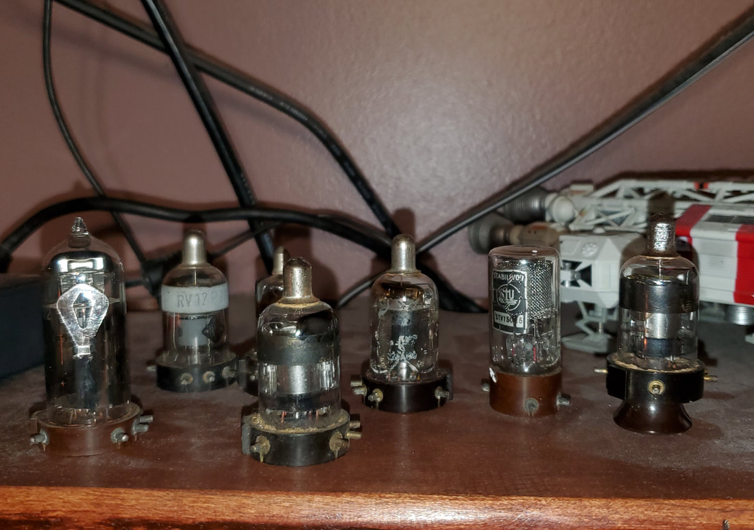 Today I made my own pin straighteners for 0.30 inch wide ICs and 0.60 inch wide ICs. This works a lot better than just bending the pins on the edge of a table. The chips are run on guides through a pair of bearings which force the pins vertical. 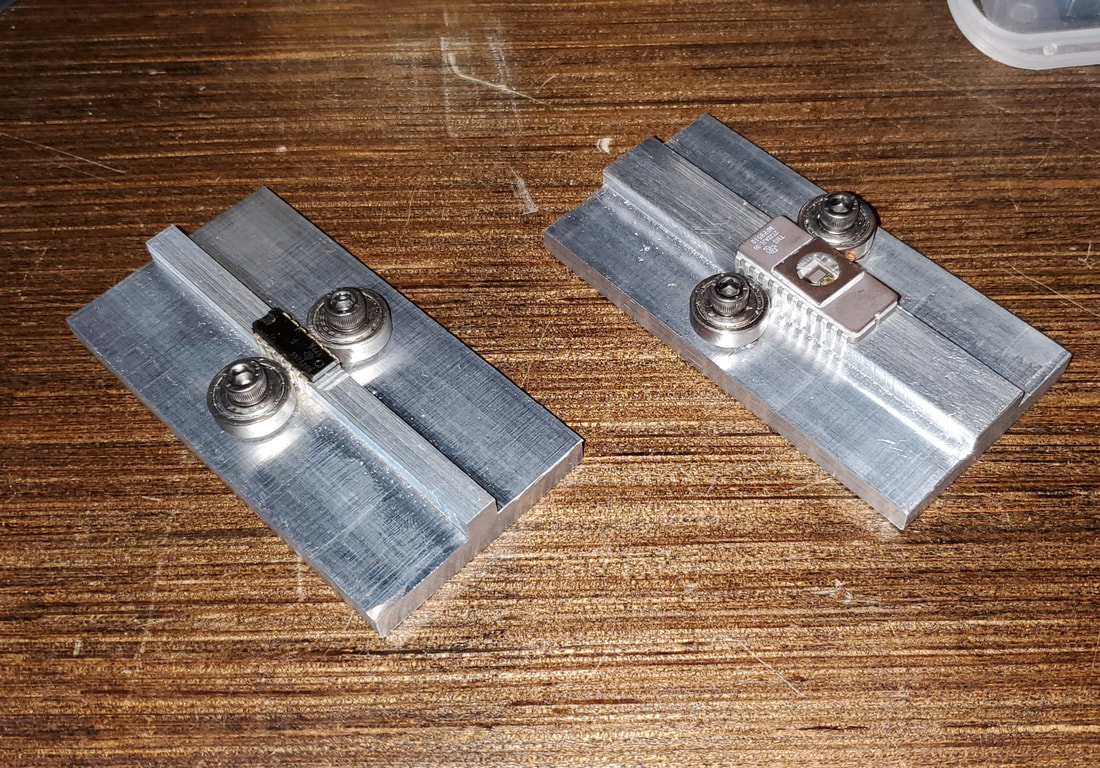 For a long while I wanted to build an Emtech ZM-2 Antenna Tuner. The kit itself always seemed way overpriced for what it is, so I decided to build one myself from parts I either already had or could order. The only things I really had to order were the T130-2 and the FT37-43 toroid cores. Most of the rest of the parts I already had. I might have had to order the two 266pF poly variable caps, but they were not that expensive either. All in all, this cost less than half the price of buying the kit. Part of the fun is making the parts. I had to make brass extensions for the variable capacitors so the knobs would fit. I have a lathe and a milling machine, so that was not much of a problem.
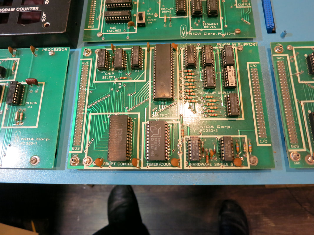
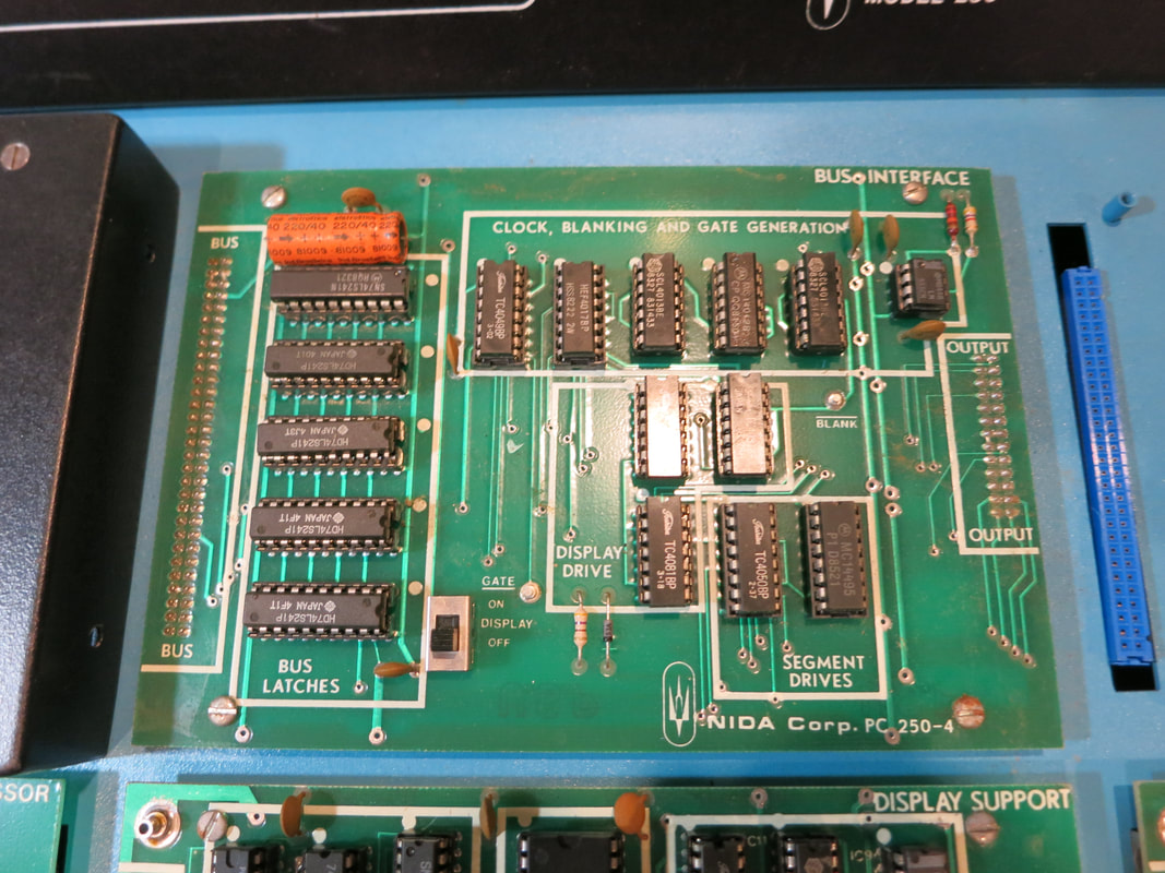
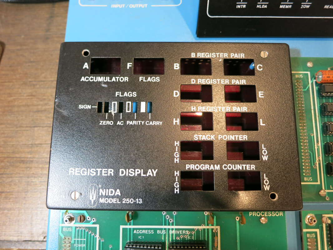
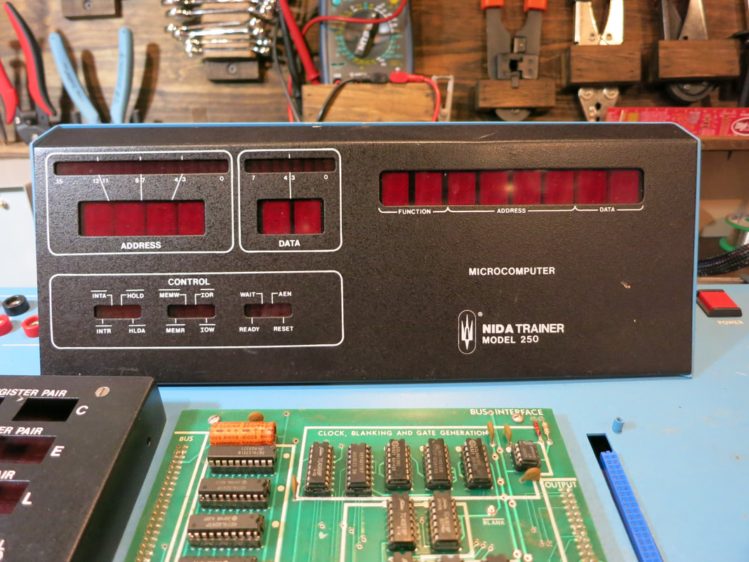
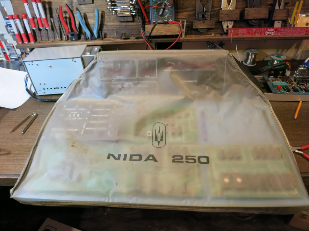
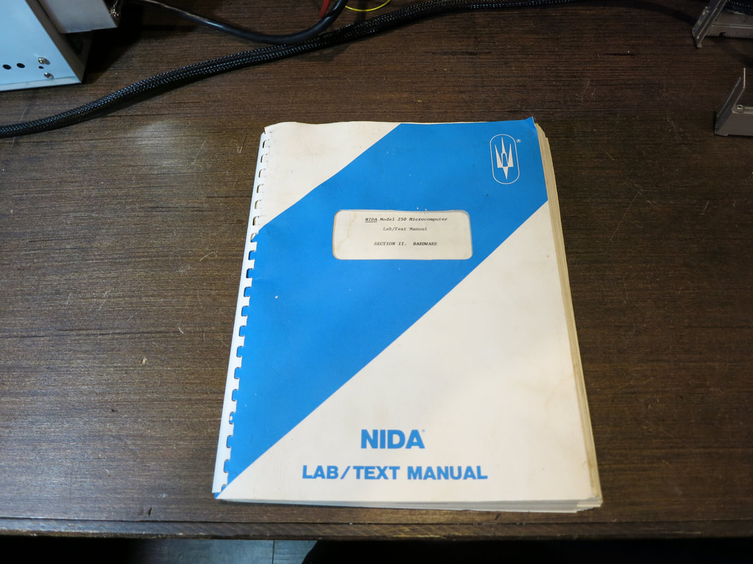
At this point, everything tested OK with my completed reproduction version of the Mod8-8 board, except I was unable to burn any EPROMs with it. What appeared to be happening was the 48 V programming voltage was not making it's way past the transistor Q5 (designated T5 in the MF8008 manual). At first I thought I might have been a missing trace, or I had incorrectly installed diode or something like that. Then I recalled that the version of the transistor I used was not in the same packaging as normal, and that maybe the pinouts were different too. Q5 (MJE1103), normally comes in an unusual TO-225 case. The version I bought on the internet (called a MJE1103T) came in a standard TO-220 case. If one views the transistor face-on (with the heatsink behind it), on the TO-225 version, the pins are (from L to R), E,C & B. I could not actually find a datasheet for the MJE1103T, but for most TO-220's the pins are (from L to R) B,C &E. Sure enough, as soon as I reversed this transistor, the proper programming voltage was making its way through, and I was able to burn a 1702A chip successfully. This essentially verified that indeed, the TO-220 version has the pins in reverse order from the TO-225 version. While reversing this transistor works, it looks kind of ugly, so I will end up ordering the proper MJE1103's. I would recommend avoiding the MJE1103T unless you cannot obtain a MJE1103 for some reason. With that, I can finally declare that the Mod8-8 board fully tested and functional with a few minor modifications. When I do the next run, I will, of course, have those corrected. 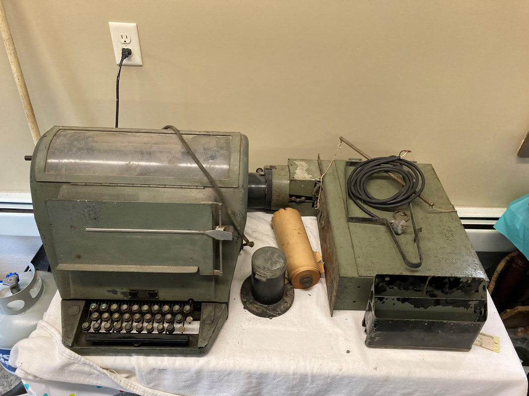 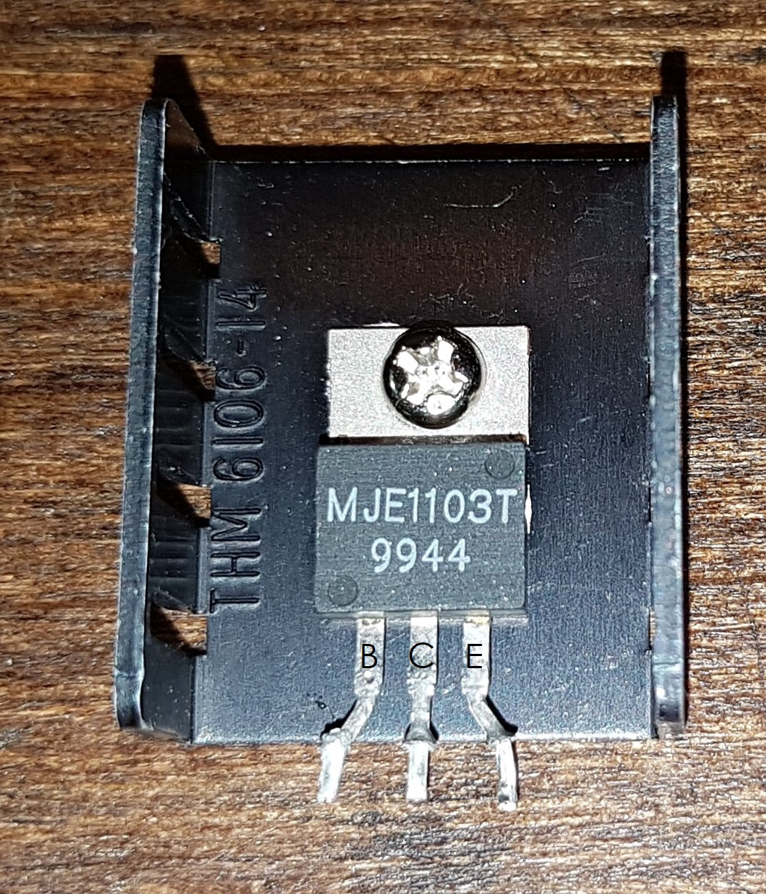  Couldn't resist. Saw this 8080 trainer at Kemners in PA a few weeks ago. Ended up buying after all. It's a Nida 250. Kinda a cool looking beast. Came with a few 2708 EPROMs as well. Doesn't seem to power up, but I am sure that can be rectified (excuse the pun) relatively easily. If anyone has manuals for this, please let me know. There doesn't seem to be anything on the net for it. Finished my board. Now I have figure out how to interpret the results! 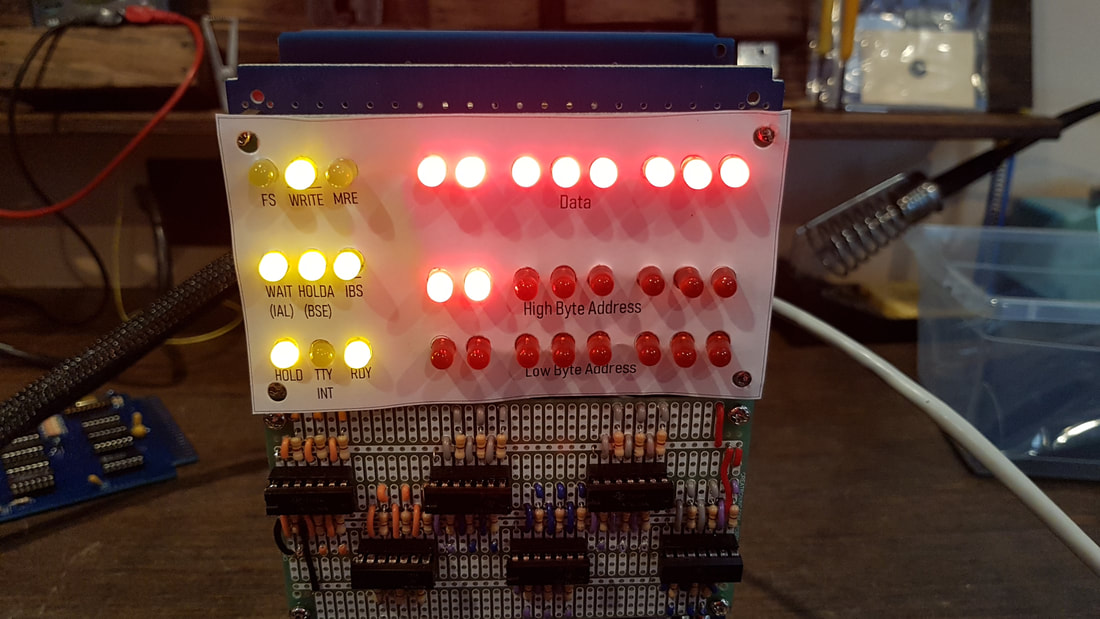 Rebuilt my 1702A EPROM programmer so that all those ugly "wall warts" are hidden in this case. Also built my latest revision of my Vintage EPROM reader for the Arduino. 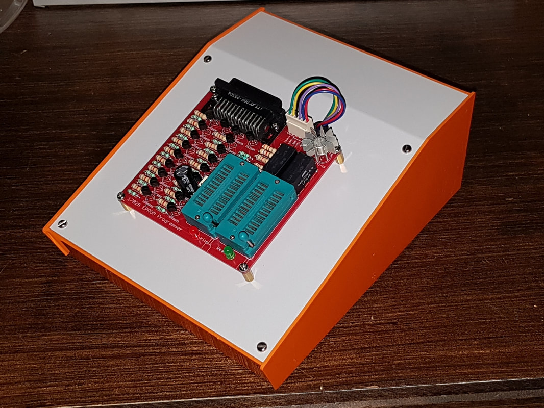 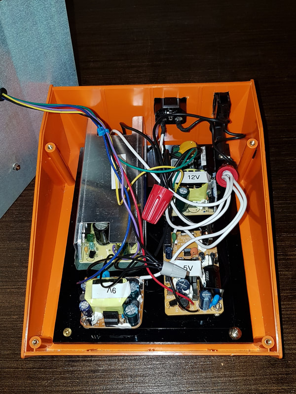 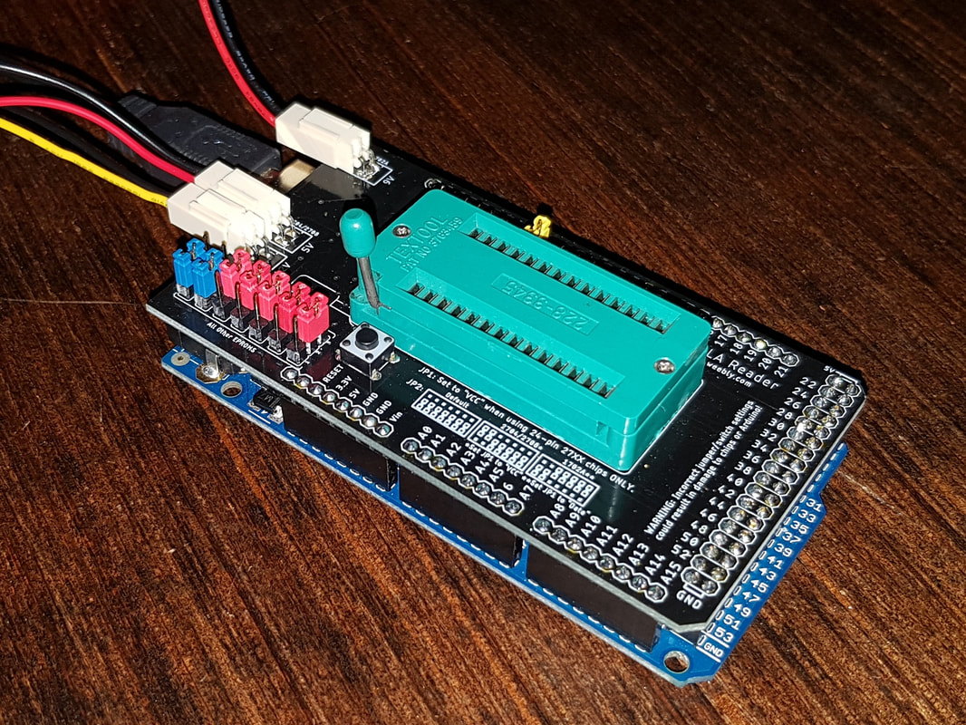 Today I received the reproduction boards that I designed from Seeed Studio in China. They look excellent. Now it is time to assemble and test them out. Hopefully there are no major errors. |

AuthorCharles Baetsen holds a Bachelor and a Master's degree in Engineering Physics from McMaster University in Hamilton, Canada. Archives
February 2024
Categories
All
|


 RSS Feed
