
BAckground
Necessity is the mother of invention - I needed a Commodore 16, Plus/4 PLA Tester
My Arduino based EPROM reader started life as a tester to test out some PLA and ROM chips for a Commodore 16 and Plus/4 that I have. There have been other plans on the net for similar shields using an Arduino Uno. Since the Uno is limited in the number of digital pins, these solutions you either read half the chip, edited the code, uploaded, and re-read the other half, or you used shift registers to expand the number of digital pins. Using shift registers requires additional code to handle these (no big deal), but the real problem is that once a set of pins is connected to a shift register, they are either input or output, and cannot be changed via software.
Since the Arduino Mega 2650 has more than enough digital I/O pins to accommodate any 24-pin or 28-pin EPROM, ROM or PLA, there is no need to add shift registers to increase the number of digital pins. This means that all the Arduino's digital pins are available for input or output via software. This is important when reading data from various EPROMs and vintage ROMs since the address and data pins are not consistent with each other. For example, on the 1702A, pin 4 is data pin D0 (which requires the applicable Arduino pin to be configured as digital input), but on all other 27xx series EPROMs, this pin is an address (A04) pin (which requires the applicable Arduino pin to be configured as digital output). Similarly, the 8316A masked ROM has a completely different pinout from a 2716 EPROM. Pin 4 is A10 in this case.
Since the Arduino Mega 2650 has more than enough digital I/O pins to accommodate any 24-pin or 28-pin EPROM, ROM or PLA, there is no need to add shift registers to increase the number of digital pins. This means that all the Arduino's digital pins are available for input or output via software. This is important when reading data from various EPROMs and vintage ROMs since the address and data pins are not consistent with each other. For example, on the 1702A, pin 4 is data pin D0 (which requires the applicable Arduino pin to be configured as digital input), but on all other 27xx series EPROMs, this pin is an address (A04) pin (which requires the applicable Arduino pin to be configured as digital output). Similarly, the 8316A masked ROM has a completely different pinout from a 2716 EPROM. Pin 4 is A10 in this case.
EPROM Reader
After experimenting with reading the Commodore 16 and Plus/4 ROMs, I wondered what it would take to read some really vintage EPROMs I have from my Mod 8 computer. These are on 1702A EPROMs, which were invented back to the early 1970s. In parallel I was building a 1702A programmer which would use two parallel ports on an old DOS based computer.
What Can it Do?
EPROMs
Basically, the EPROM reader can read any of the following ICs (and their variants, i.e, 27C128 etc.):
* Requires an external 9V supply
** Requires an external 5V and 12V supply. 2704 & 2708 have not been tested.
- 1702 and 1702A EPROMs* (including variants such as 1301, 1302, 1601,1602, 1701, 4702A, 8702A etc.)
- 2704** EPROM
- 2708** EPROM
- 2716 EPROM or 2316 ROM or 8316A ROM
- 2732 EPROM or 2332 ROM
- 2764 EPROM or 2364 ROM
- 27128 EPROM or 23128 ROM
- 27256 EPROM
- 27512 EPROM
- 8316A ROM
- 6830A ROM
* Requires an external 9V supply
** Requires an external 5V and 12V supply. 2704 & 2708 have not been tested.
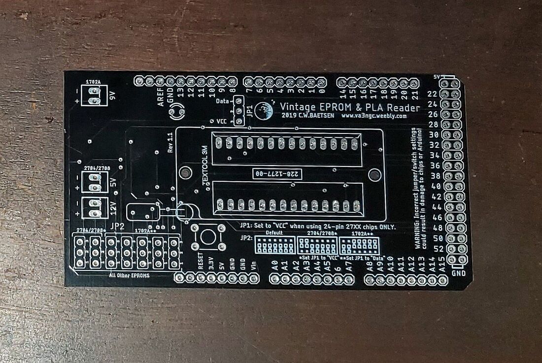
Buy your own Arduino Shield PCB
|
Boards for sale. If you are interested in buying PCBs to build your own "Universal Vintage EPROM Reader Shield", then email me. PCBs are $10.00 USD each plus shipping.
|
Software and Manual
Click on the links below to download a copy of the latest build manual and Arduino sketch for using the shield.
Last updated on October 24, 2023 (Links fixed)
