
A basic barn-door drive consists of two boards hinged together at one end, and spread apart by a screw that turns at a constant rate to counteract the motion of the earth (see figure 1b). The basic problem with this design is that the rate of change of the angle between the two boards is not constant with a constant speed of the screw. This problem is known as tangent error and is a consequence of geometry. Normally this is not a problem unless you want to take exposures longer than 15 minutes (using a 50 mm lens). In an attempt to counteract this effect, several designs were described in this article that use two arms instead of one. None of these can eliminate the effect entirely, but they can reduce it enough to allow for exposures up to 2 hours. Of these, the type 4 drive was the best at minimizing this error.
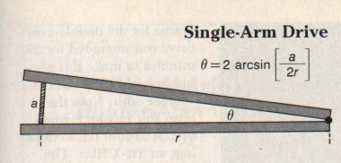
Figure 1b - Basic Barn-door design (from Apr '89 Sky & Telescope)
Modifications
The original design consisted of an L-shaped secondary arm, supported by a rectangular primary arm (see figure 1c). This means that the drive is larger than it needs to be. To increase the portability of the drive, I placed the secondary arm inside the primary arm (see figure 1a), thus reducing it's width.
The original design consisted of an L-shaped secondary arm, supported by a rectangular primary arm (see figure 1c). This means that the drive is larger than it needs to be. To increase the portability of the drive, I placed the secondary arm inside the primary arm (see figure 1a), thus reducing it's width.
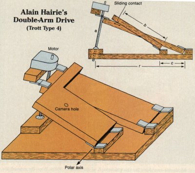
Figure 1c - The original type-4 barndoor design (from Apr '89 Sky & Telescope
Modifications
One difficulty worth noting, was obtaining a suitable trunnion (the pivoting device that hold the lower end of the drive screw). The design shown in the article required machining and welding, both of which are a pain, unless this happens to be your profession and you have access to the proper equipment. After many failed attempts to improvise, I found a solution. The greatest thing about this solution is that it requires no more sophisticated equipment than a drill. What I did, is drill two dimples, 180 degrees apart on a 1/4-20 SS nut. Then I suspended the nut between two binding posts, using nails as pivoting points (see Figure 2 below). It works perfectly.
One difficulty worth noting, was obtaining a suitable trunnion (the pivoting device that hold the lower end of the drive screw). The design shown in the article required machining and welding, both of which are a pain, unless this happens to be your profession and you have access to the proper equipment. After many failed attempts to improvise, I found a solution. The greatest thing about this solution is that it requires no more sophisticated equipment than a drill. What I did, is drill two dimples, 180 degrees apart on a 1/4-20 SS nut. Then I suspended the nut between two binding posts, using nails as pivoting points (see Figure 2 below). It works perfectly.
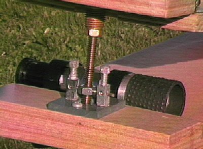
Figure 2 - Close up of the trunnion and polar alignment scope
Specifications
r = 16.656"
b = 10.000"
c = 4.575"
Screw: 1/4"-20 TPI (brass or SS threaded rod)
Motor: 1 RPM
Lessons Learned
Use good brass hinges. This will save you lots of hassle in the long run, plus they will not rust.
Don't use oak or any other wood that will warp. It is best to go out and buy a small sheet of 1/2 inch Baltic Ply. It doesn't warp and it looks fantastic
Improvements
There are two improvements I would make if I were to do it again. They are:
Replace the ball joint camera mount with a mount that allows independant rotation in all 3-axes. This way I could better "frame" any pictures.
Make the whole thing 1/2 the size and use a 1/2 RPM motor (or stepper motor) to make the whole thing just that much more portable.
All in all it was not a terribly difficult project. If you can cut wood, you can build a barn-door drive.
