
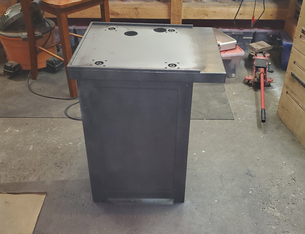
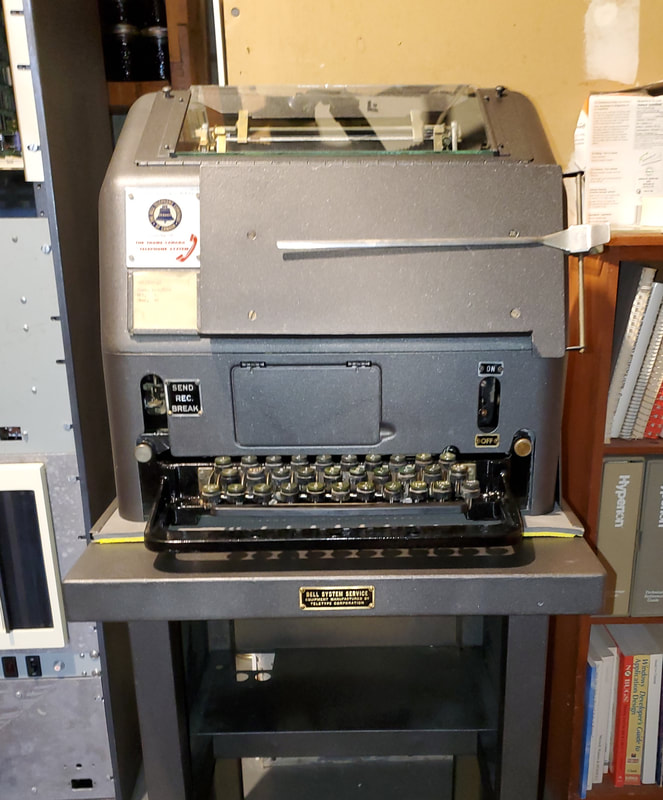
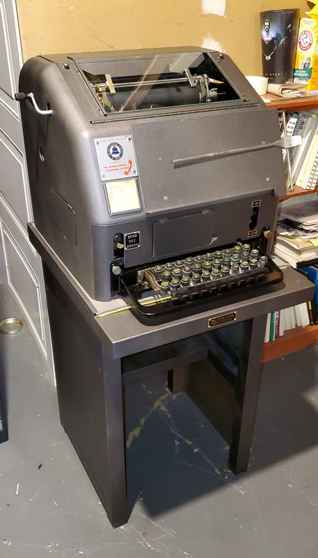
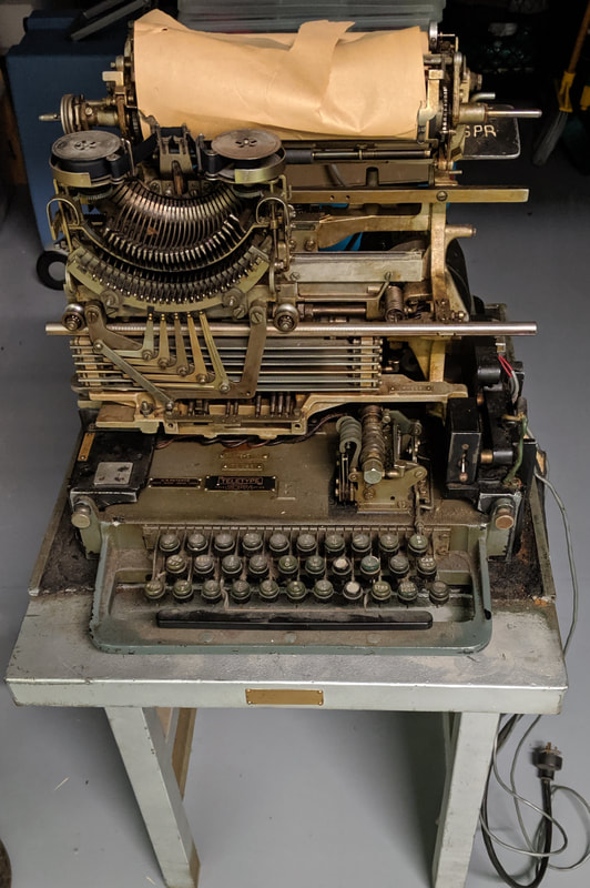
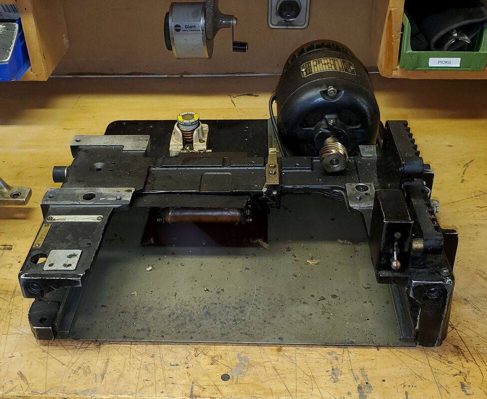
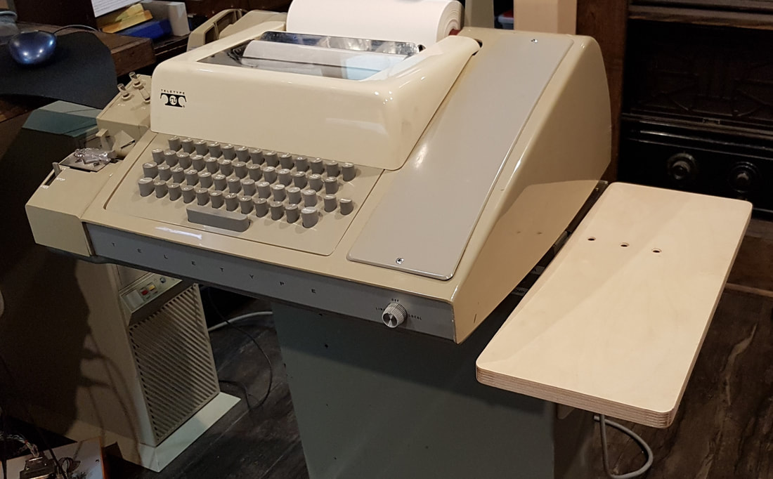
I finished giving the Model 15 and table a new paint job, which turned out really well.
|
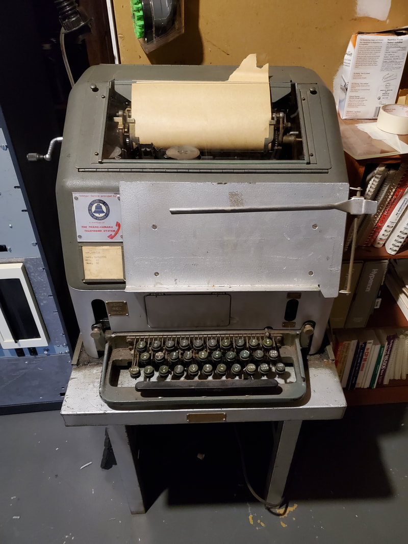
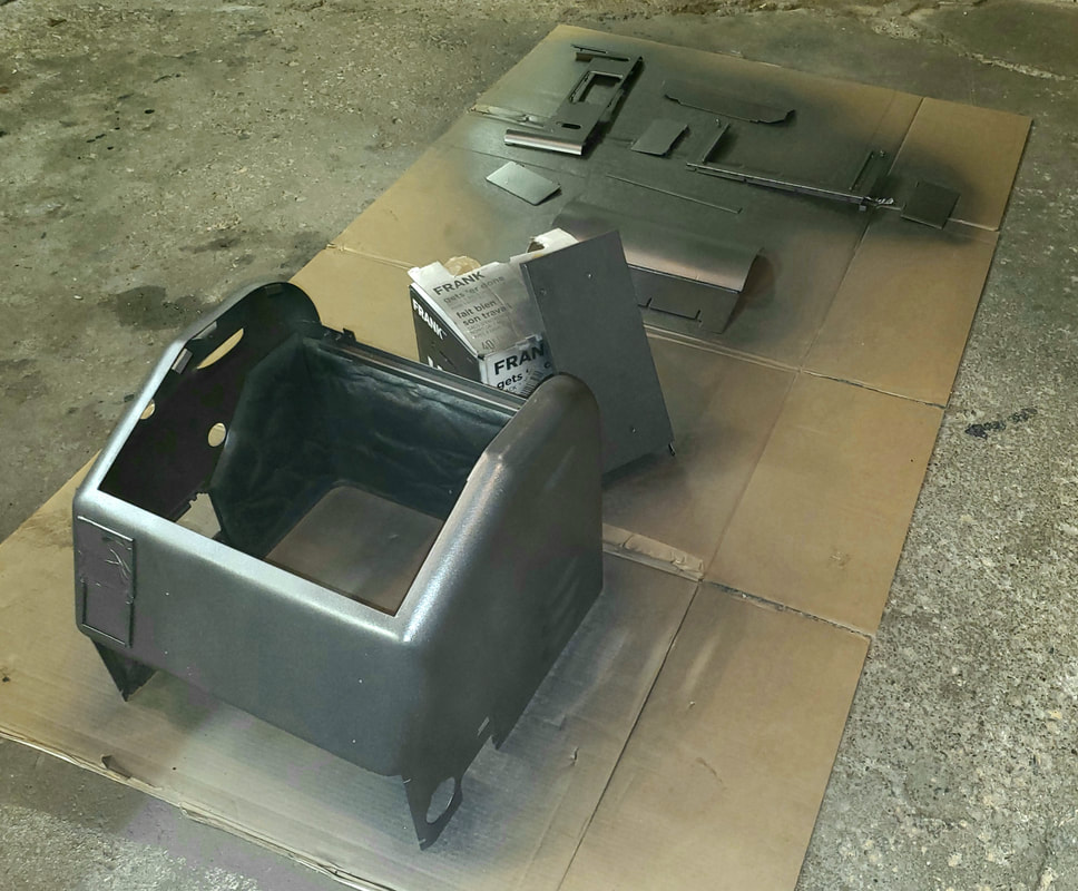
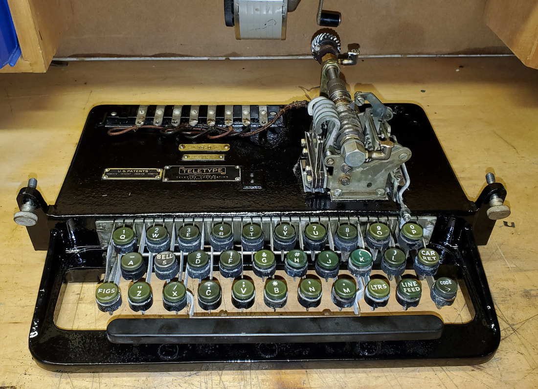
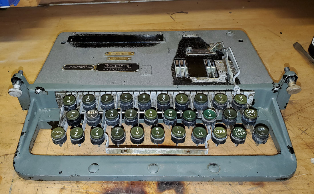
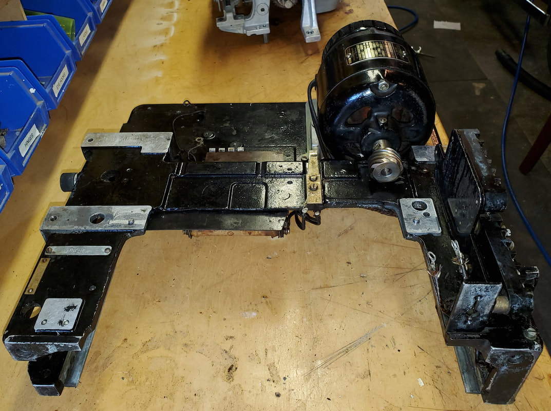
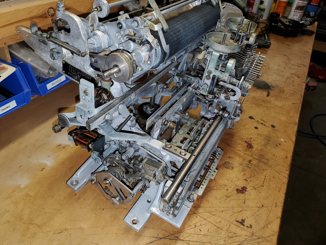
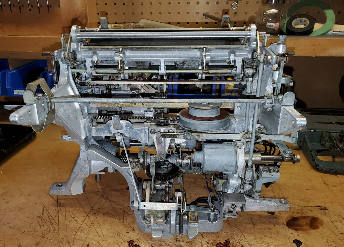
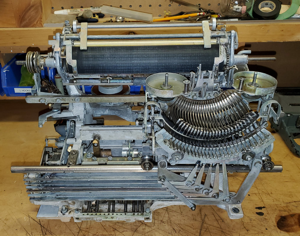
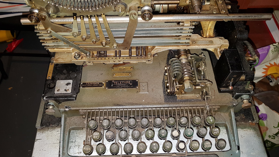
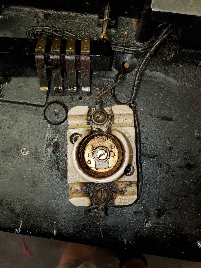
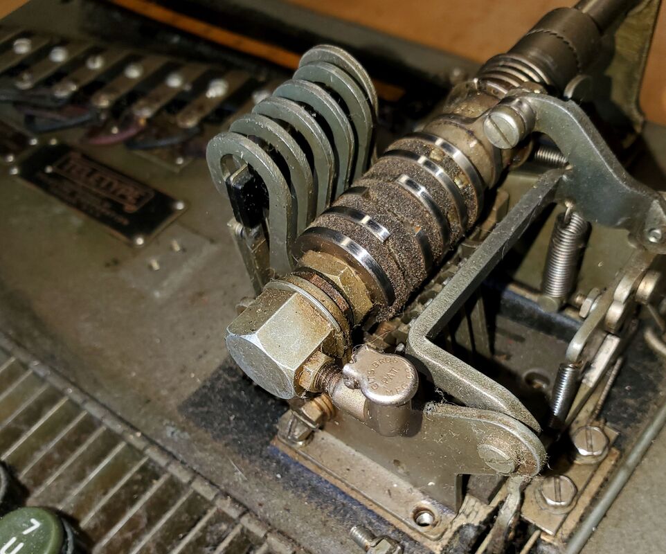
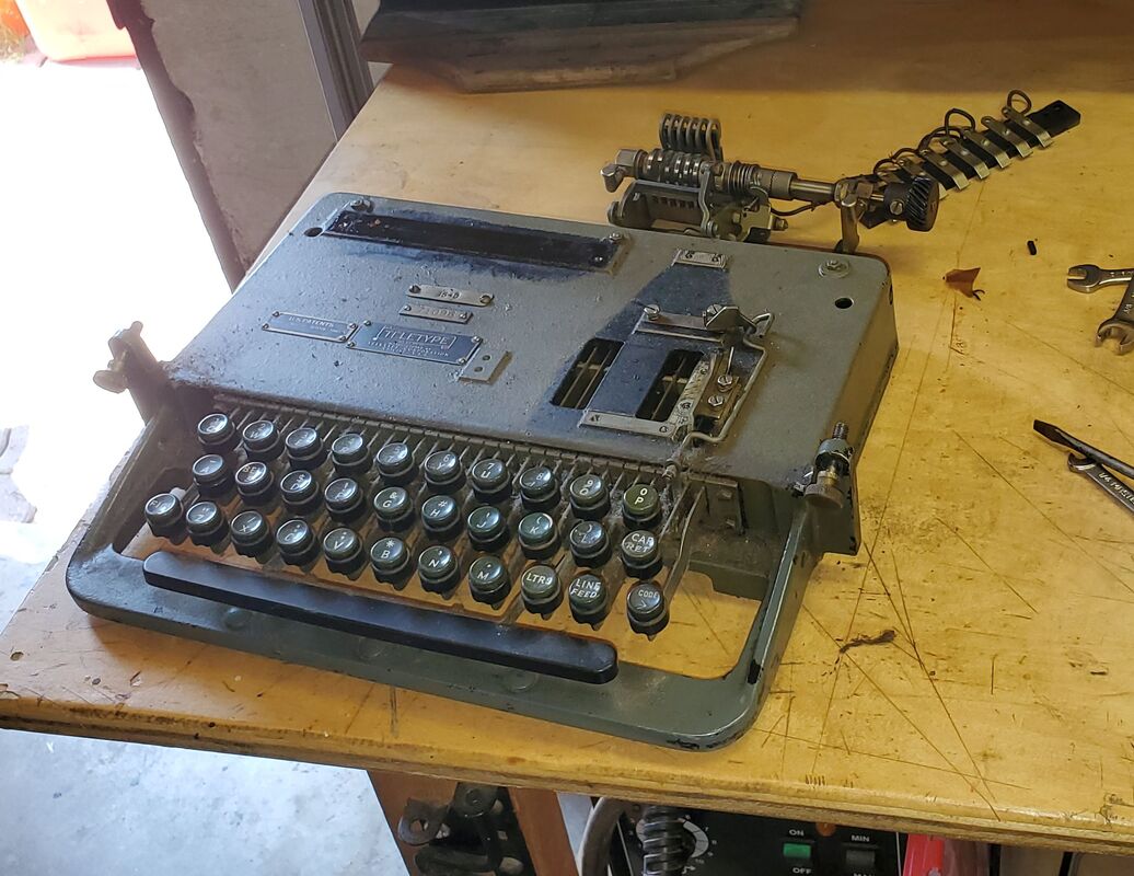
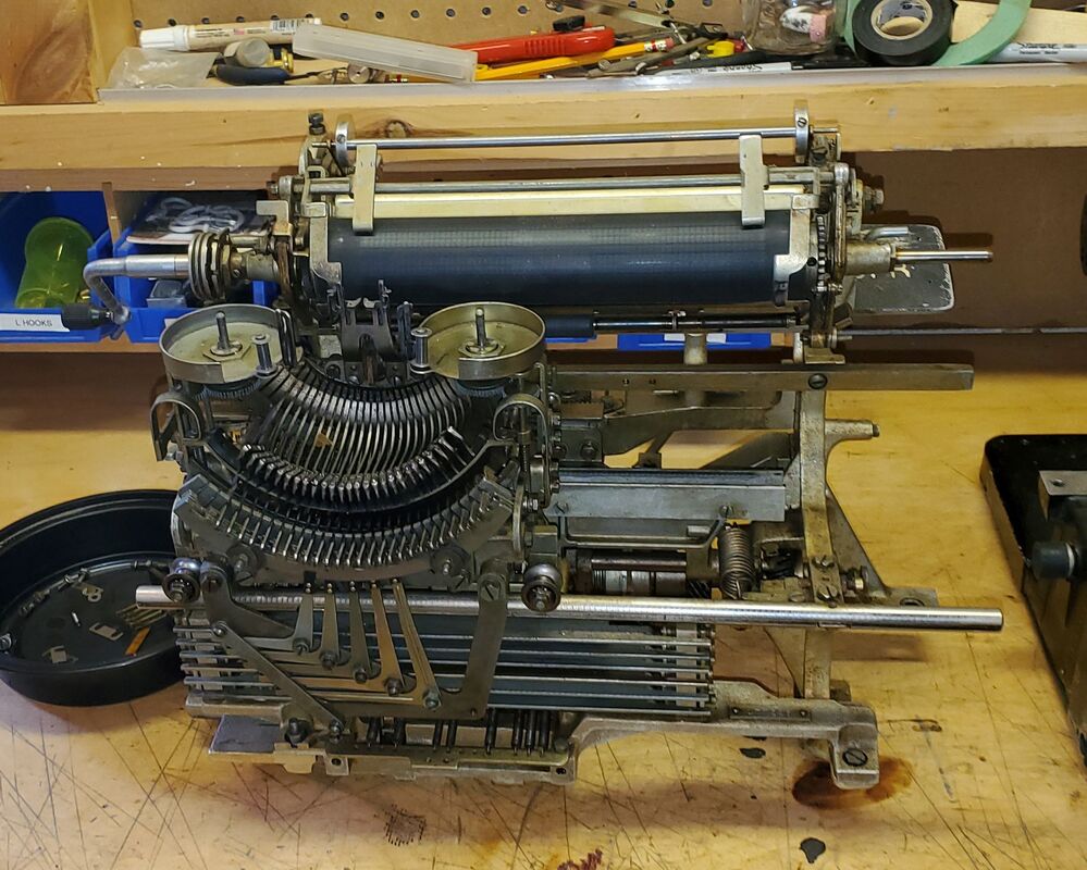
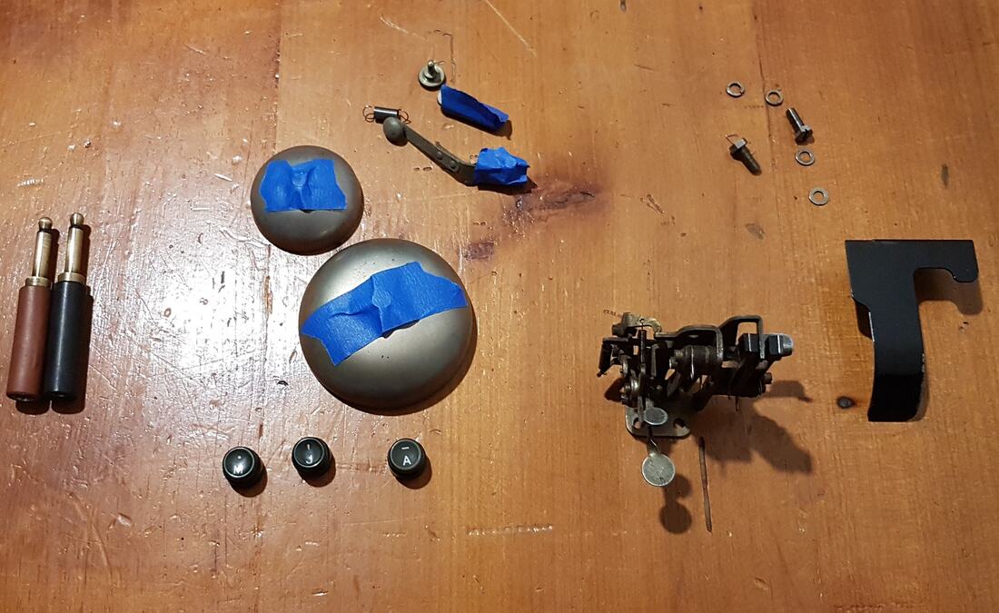
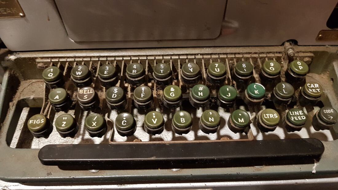
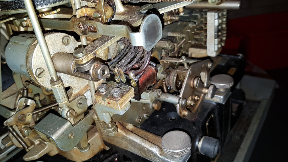
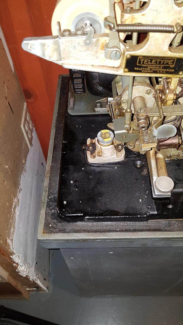
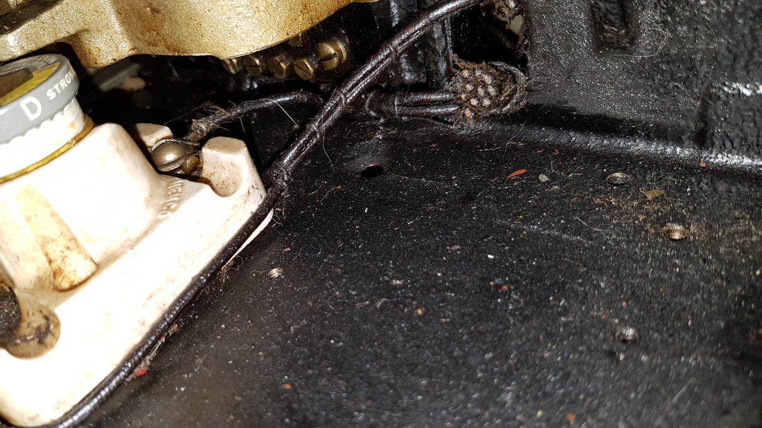
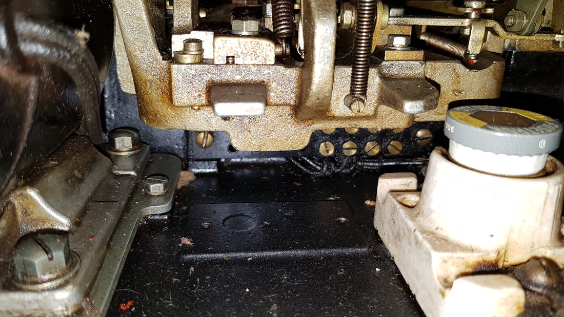
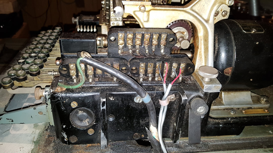
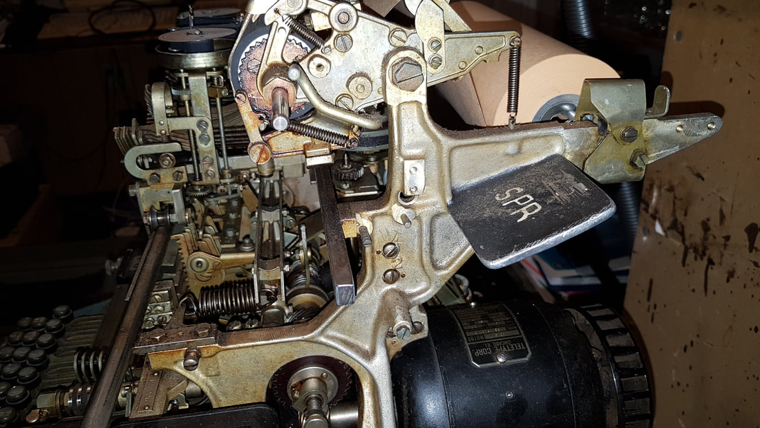
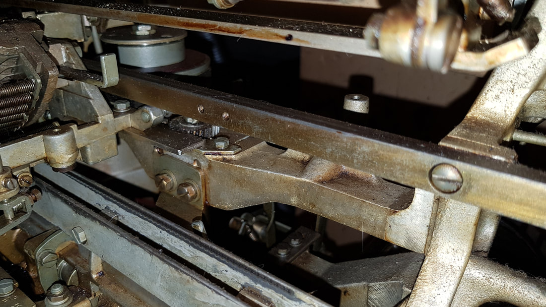
This is the teletype table. It had this supposed felt pad to keep vibrations under control (see center picture). What ever this material was, it pretty much crumbled to bits. Interestingly enough, it has "June 22, 1960" stamped on it. So the teletype was likely made then. 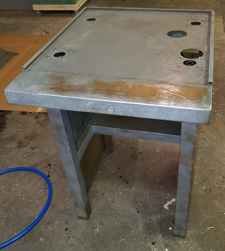 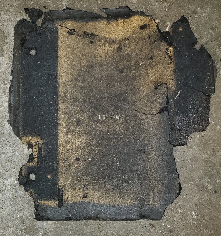 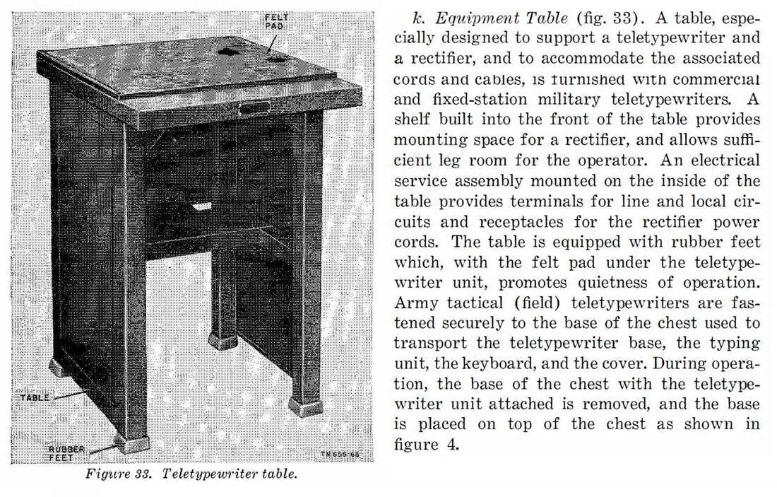 Model 15 Restoration: keyboard painted, put back together and lubricated. This part is ready to go. It's a very clever device. There are 5 levers that extend below the top which get set by each key press. It's all done with notches in bars. These levers represent the Bardot code for each character (similar to ASCII binary codes used in your computer). Then the little rotating shaft sends these out serially by moving the hook like pieces one at a time. Elegant. Model 15 Teletype Restoration: These cleaned up really well with some Spray Nine degreaser and water. I'm impressed. They were originally filled with hardened grease, old oil and gunk. Today I decided to start the restoration of my Model 15 Teletype. This is a neat machine that was in production from 1930 to 1962 or so. It is entirely electro-mechanical. First step is to take it all apart and clean all the gunk off of it. Then oil and re-assemble the mechanical parts. I also may paint some sections as appropriate. I picked this teletype up at a garage sale back in July 2019. In October of that year I was thinking of getting this thing working, but I just did not get around to it. Now two years later it is time to give this baby a try. Fortunately there is a lot of documentation on the internet, and Curious Marc did a similar restoration on a Model 19 which is essentially the same machine. Got some missing parts for my Model 15 Teletype, including some key caps. Believe it or not, there is this guy in California that has a shed full of parts for these things. I emailed him what I wanted (using the part #'s from the manuals) and he found what I was looking for and sent them to me for a modest price. Below are some of the odds and ends I bought. For some reason the margin bell and the bell that can be rung remotely via a baudot command was missing as well.
Yesterday I picked up this Teletype Corporation Model 15 teletypewriter at a local garage sale. Apparently the owner picked it up at a Goodwill auction about 20 years ago for $75.00. He intended on making a steampunk type setup with a raspberry PI or Arduino driver to display twitter or other messages on the machine, but never got around to it. After some intense negotiation (friendly, but intense), I managed to walk away with it, and a Teletype Modem for $150. He knew it was going to a good home, so I think that helped. I promised to email mail him pictures and links once it was restored and operating. It appears to be missing some components, so it will take some time to restore. There is no SEND/REC/BREAK switch, and both the margin and alert bells are missing. The control relay is missing as well, however it is not clear as to whether or not all this was because it was cannibalized to fix another teletype, or it was a variation in design. This will be fun to play with. I love these old electro-mechanical devices. This one looks a lot simpler, though still fiendishly complicated, than the insides of the ASR33 I have. 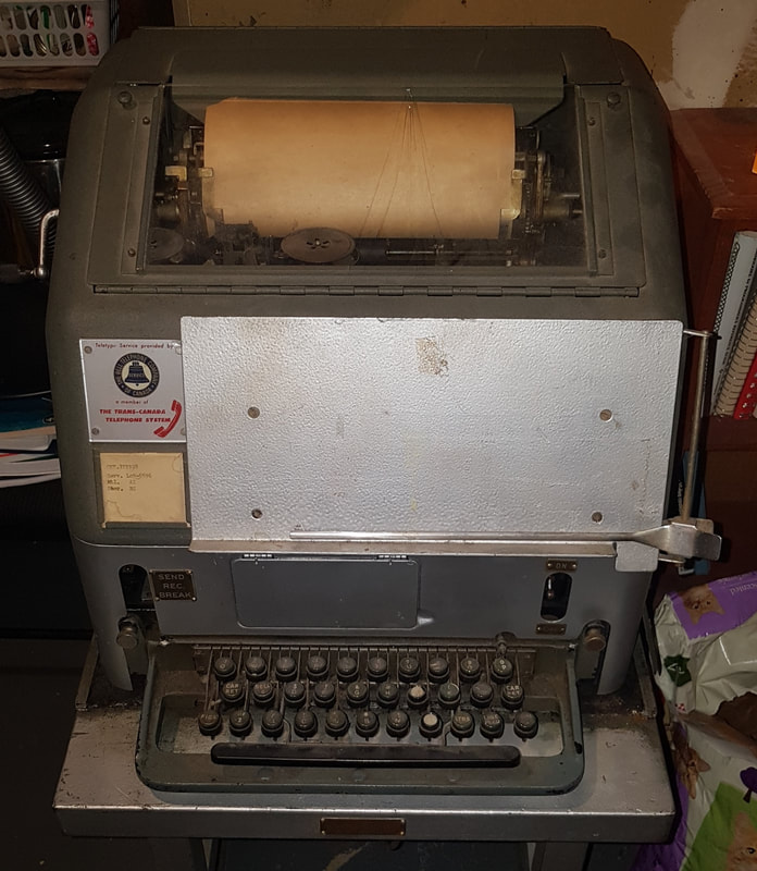 Model 15-D Teletype Today, I decided to attempt to burn a 1702A EPROM using the Mod-8. As you can see from the video below, it went pretty smoothly. To burn data on an EPROM, you enter the command PRG. Monitor-8 responds with the '*' prompt and awaits the user to enter the start and end addresses of where the data is stored that you want to burn on the EPROM. After entering the final address, Monitor-8 responds with the '%' prompt. Possible responses are 'A', if using a 1702A chip, or 'N' if using an older "normal" 1702 chip (which I have never seen). Typing an "A" will give a program pulse duty cycle of 20%, and typing an 'N' gives approximately 2% duty cycle. After entering either 'A' or 'N', the computer will immediately beginning programming the chip. When I first tried this, I thought something went wrong, as the teletype started making some chattering noises. Apparently this is normal and serves as a sort of audible indication of the programming as the chattering matches the blinking of the programming LED on the back plane. The Mod-8 burns an EPROM as follows. Instead of burning the entire chip and then verifying it, it will burn each byte individually and verify the contents are ok before moving on to the next byte. If the burn was not successful, it will re-burn the byte and verify it again. It will continue to do this until the burn takes. Healthy EPROMs take slightly less than a minute to burn, whereas poorer chips may take several minutes to burn, as the number of re-burns will be higher. Interestingly enough, these chips are only mildly warm to the touch when they are finished, much different than what I noticed with my 1702A EPROM burner for the PC. Not only can you write data to the EPROM in the ZIF, but you can read it as well. Monitor-8 uses memory locations 200000-200377 to access the EPROM data. You can also use 300000-300377 as well. Notice these ranges are well outside the 16 kB address space normally accessible to the 8008. If using Monitor-80, the above address locations could represent real memory locations in RAM (or ROM), so to read EPROM memory, you use P000-P377 instead. Below is a video of how programs (in this case, "Hangman") is loaded from paper tape on the MIL Mod-8 Computer.
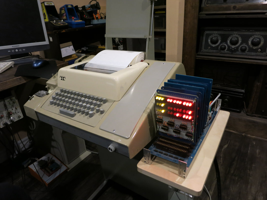
Made my own version of the Optional 343691EW modification kit for the ASR 33 so I could provide a shelf for my Mod 8. It works perfectly. The unfinished wood looks like it was an original part too! |

AuthorCharles Baetsen holds a Bachelor and a Master's degree in Engineering Physics from McMaster University in Hamilton, Canada. Archives
February 2024
Categories
All
|


 RSS Feed
