
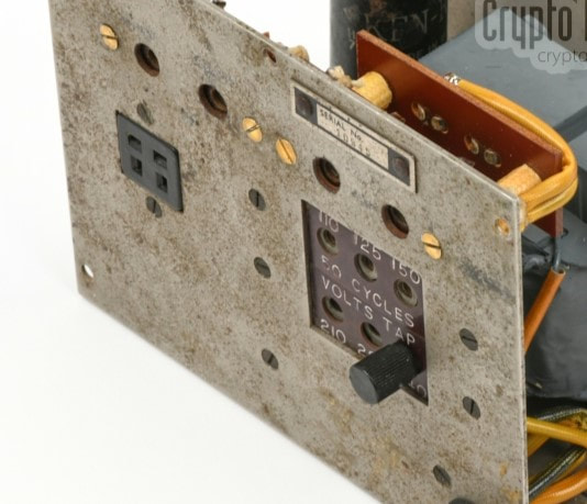
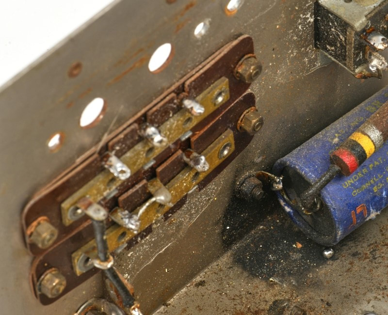
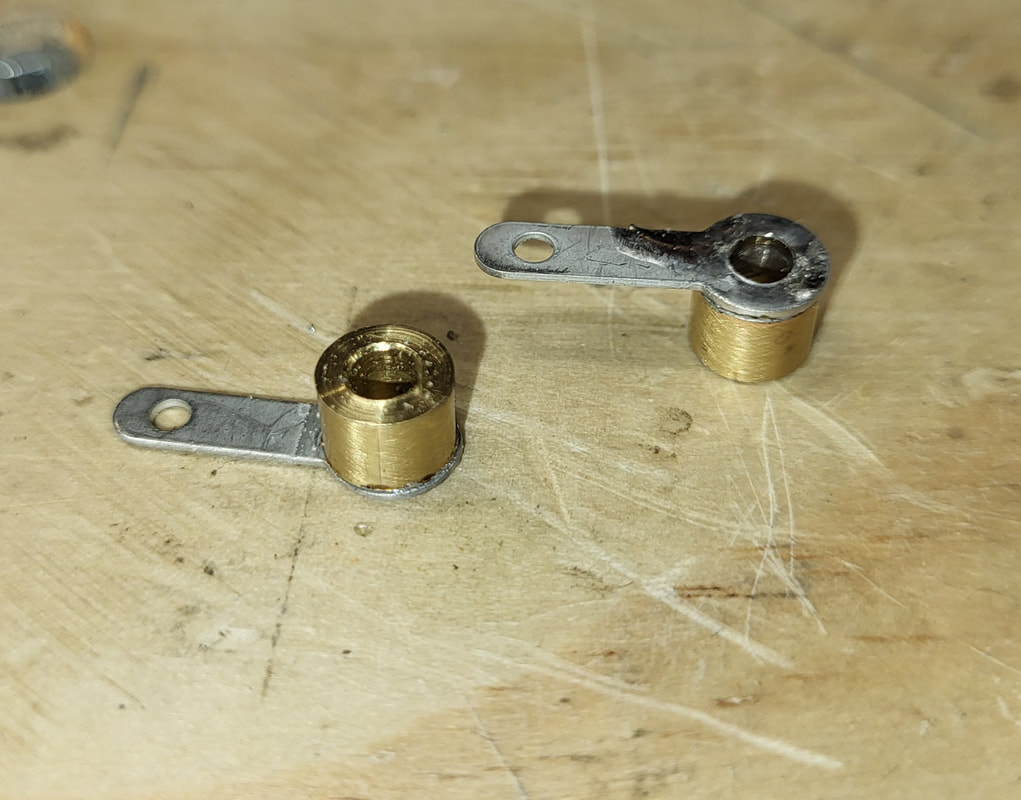
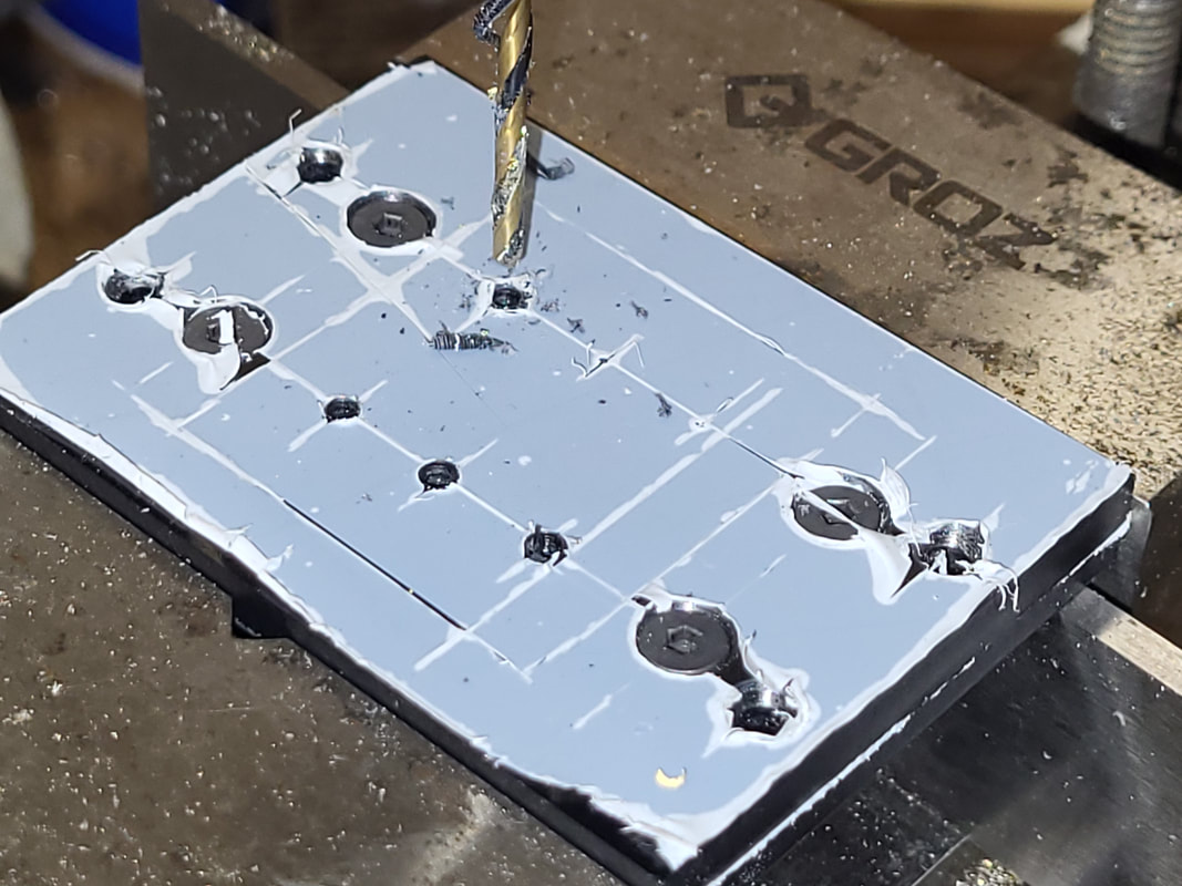
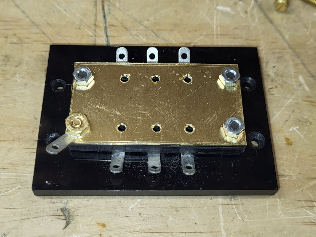
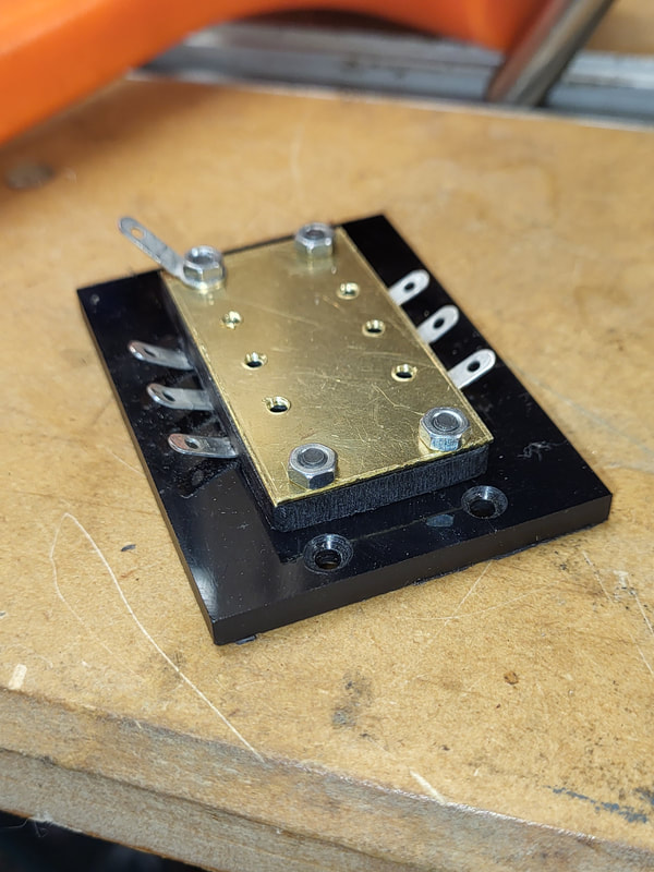
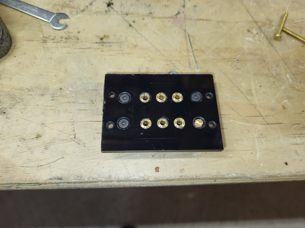
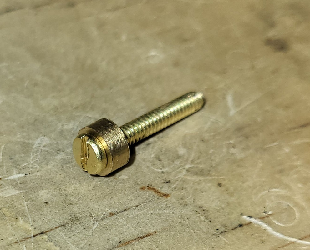
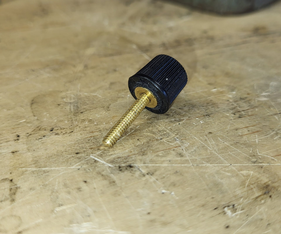
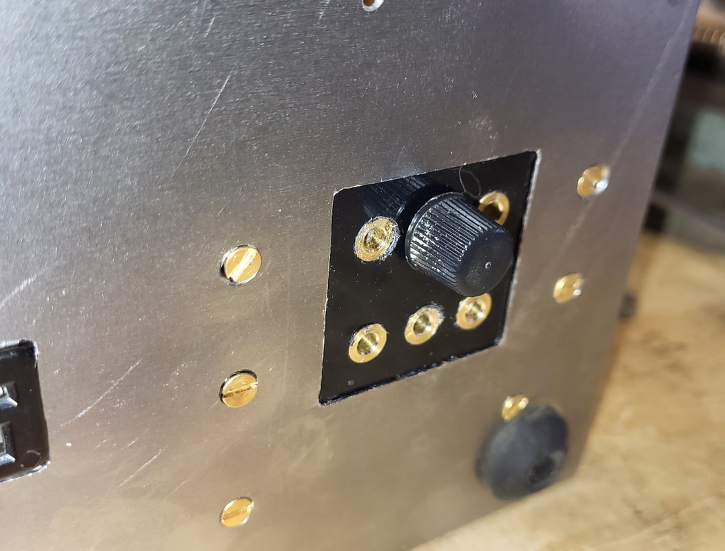
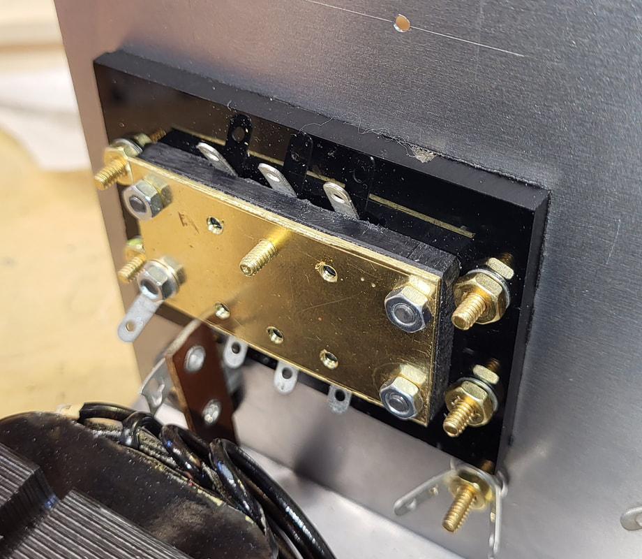
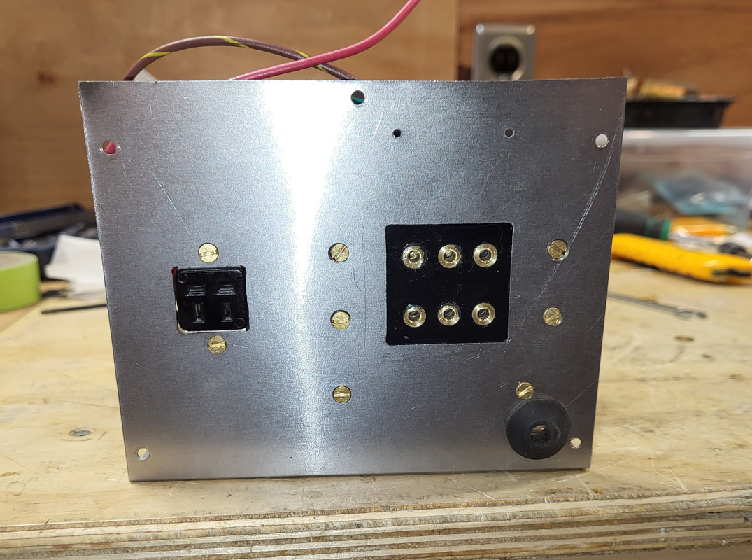
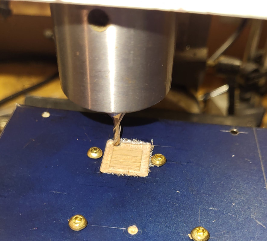
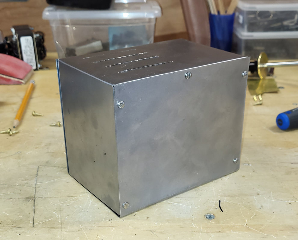
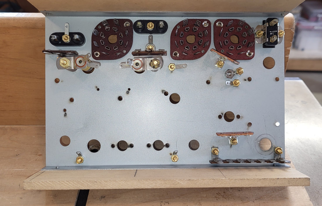
Now that the Paraset Power Supply case is completed, I needed to make a reproduction voltage selector panel. On the original PS, the user could select one of 6 different input voltages from 110 to 240 VAC. Since I used a multi-tap transformer, I could actually reproduce that functionality. This required making up some specialized pins etc., to best match the original.
|
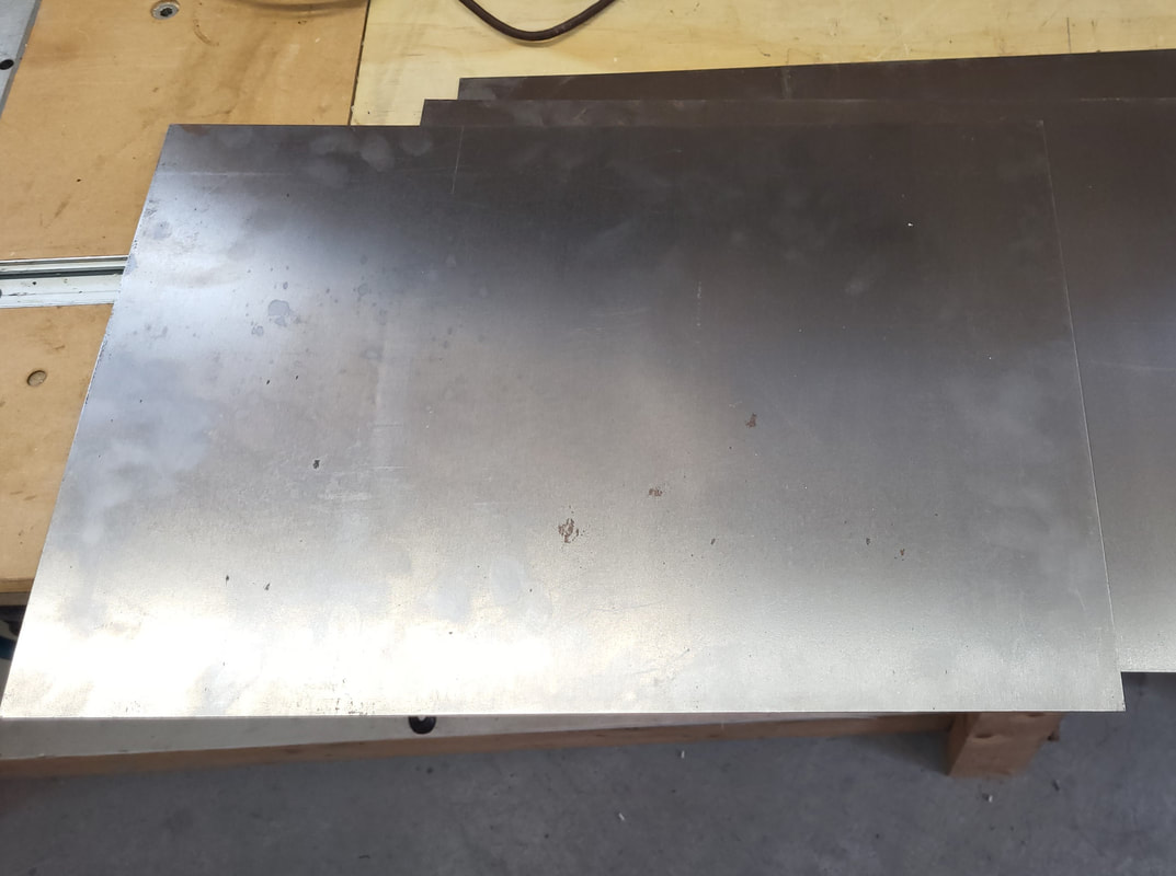
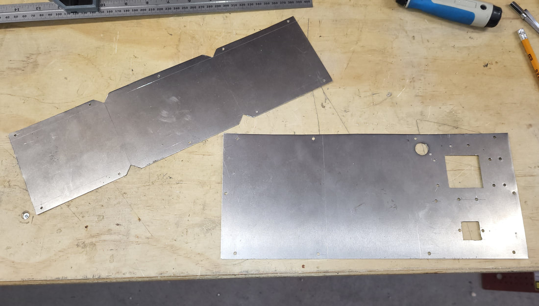
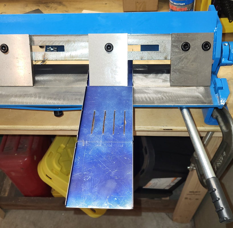
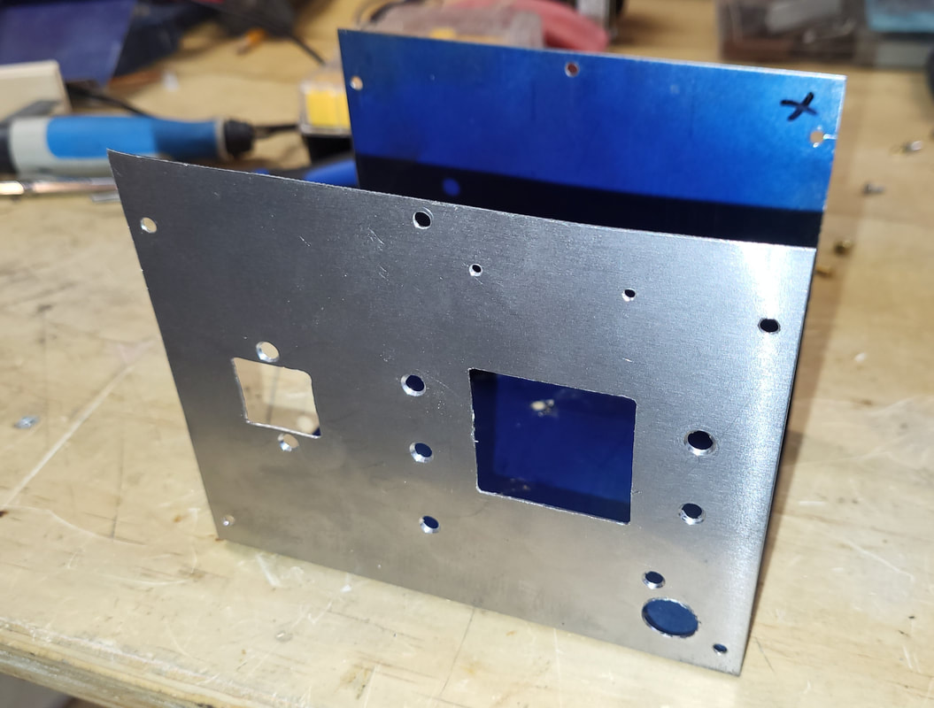
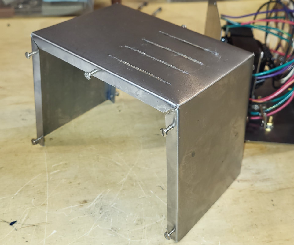
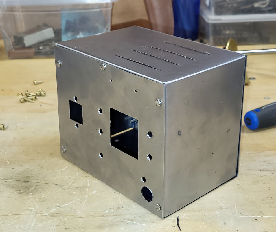
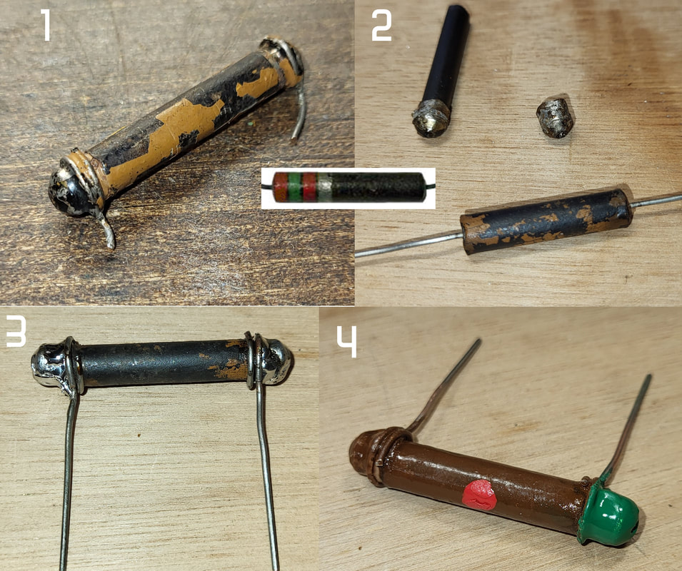
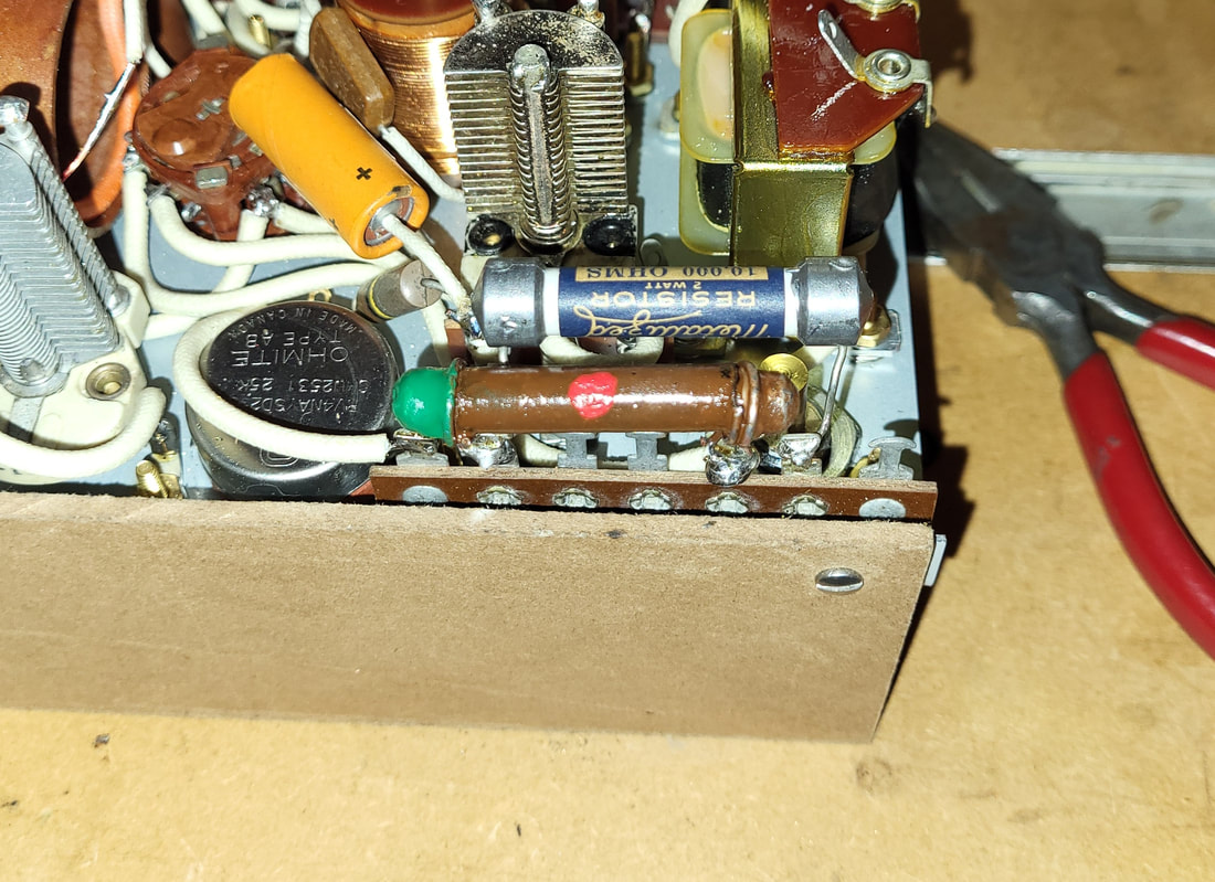
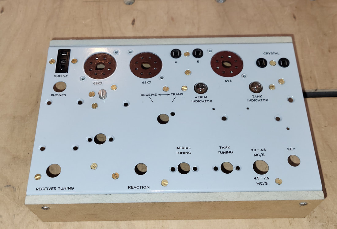
Started working on the case for the Paraset power supply. The first attempt was a bit of a learning process. I ended up redoing the cover as I goofed and I also needed a heavier brake to bend the metal than the cheap one that I used for thinner metal or Aluminum. I also decided to redo the bottom as I am not happy with some aspects of it. Having a new bending brake made things a lot easier for. I "think" I am finished soldering my Paraset. It is always possible I missed something, but I hope not. Now it is time to make up the power supply and do the sheet metal work. 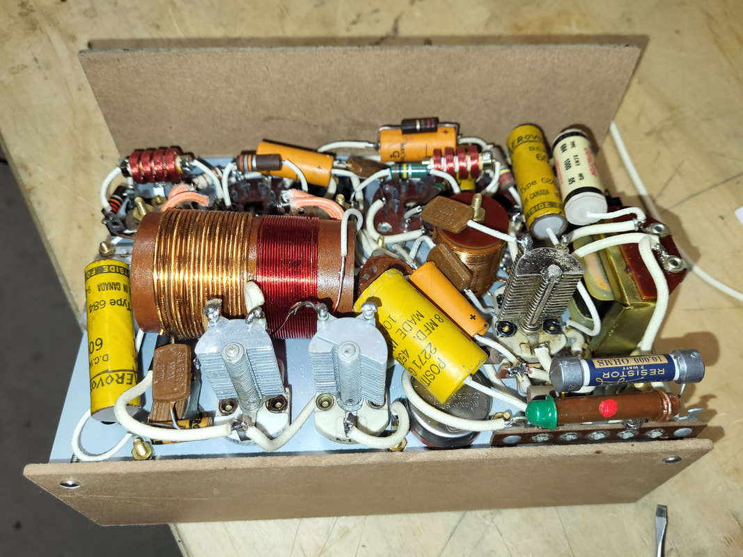 I made up a vintage dogbone resistor for my Paraset using an old one and inserting a standard colour coded resistor inside so that it had the correct resistance. Then I gave it the correct paint coding on the outside. Did some soldering this weekend. Nearly finished soldering the Paraset together. Getting much closer. Finished making the receiver and transmitter coils. Made up some vintage looking capacitors. Just need to wax dip some of those. Then I can start wiring up the unit Finished preparing the front panel for my Paraset radio. Now I can start installing and soldering in components. |

AuthorCharles Baetsen holds a Bachelor and a Master's degree in Engineering Physics from McMaster University in Hamilton, Canada. Archives
February 2024
Categories
All
|
 RSS Feed
