As you can see, the EPROM I am programming here is for my Ithaca Audio Floppy Disk Controller.
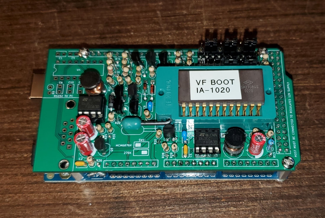
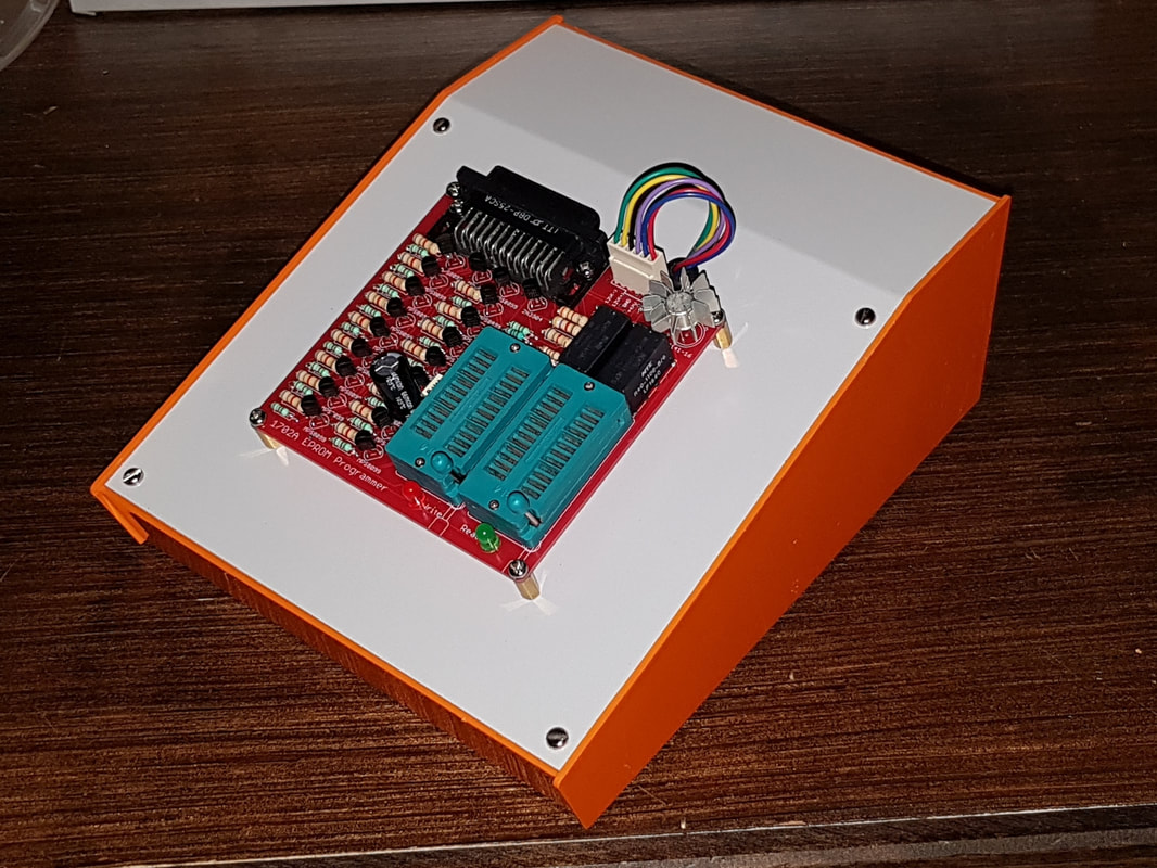
I purchased this Matt Millman's 2708 programmer shield (unpopulated) for the Arduino Mega 2560 R3. This allows me to program 2708 chips, something I cannot do with any other programmer I own. It will actually program 2704 / 2708 / TMS2716 / MCM68764 and MCM68766 EPROMs. The only one it will not program is the 1702 / 1702A. However, Matt has a board for that too. Unfortunately, that board is nearly made entirely of surface made components, so it would be tricky to put together.
As you can see, the EPROM I am programming here is for my Ithaca Audio Floppy Disk Controller.
0 Comments
Making an adapter for my Optimal Technology EP-2A 2708 programmer, so I can attempt to program some 2708's using an Arduino UNO. If this works, this could lead to a very simple Arduino shield for the UNO to program 2708's since the EP-2A uses only 3 ICs which are still readily available.
What I done so far is use a 44-pin cable connector and wired it up to a small PCB which in turn connects signals to an Arduino proto-shield via a ribbon cable. The PCB also will connect to the various voltages needed (not yet wired up). The ribbon connector on the Arduino proto-shield will be connected to 12 of the Digital pins available on the UNO (8-for data and 4 for control). Interestingly enough, the EP-2A does not need address information. It auto advances the address based on a clock signal (one of the 4 control signals) sent from the computer (or in this case the Arduino). Rebuilt my 1702A EPROM programmer so that all those ugly "wall warts" are hidden in this case. Also built my latest revision of my Vintage EPROM reader for the Arduino.
Based on some things I discovered during testing of the first board I made up, I decided to change it a bit. One thing that was evident, was that the +5V from a digital pin going high, may or may not be enough to power an EPROM. To accommodate that, I added a series of jumpers so I could select certain pins being connected to the Arduino digital pins, or external power. This is the result. I was hoping to use DC-DC converters to generate the other voltages needed (-9V, -5V, +12V) for older EPROMs, however, they do not seem to provide enough current for reliable chip reading. In the case of the 1702A, I resorted to a good old 9V battery. It worked quite well. Now I can read all my Mod 8 / Mod 80 EPROMs. Got the boards I created from China. They look pretty good. I am quite happy with them. Just waiting on some DC to DC converters so I can test it out on the really vintage EPROMs (i.e., 1702A, 2704, & 2708).
I have a Commodore 16 and a Commodore Plus/4 that do not work. These are notorious for failing due to some of the chips overheating. I've tried getting these two to work without success thus far. Since I don't have access to a working machine to test which chips are working and which ones are not, I decided to build a test unit using an Arduino UNO to at least eliminate a few of the possibilities. This is what I came up with. It function is to test the C16 and Plus/4 PLA (Programmable Logic Array) and ROM chips. Now that the hardware piece is finished, it is time to do the coding.
I used to have one of those La Crosse weather stations, however my rain gauge stopped working, and eventually, my temperature sensor died as well. This is the second time that happened, so I decided to try something completely different.
I purchased a SparkFun Weather Shield and hacked some of my old La Crosse weather instruments from my dead weather station to make a personal weather station using an Arduino, an Electric Imp. You can now see my weather on Weather Underground. I even went so far as constructing my own Stevenson enclosure for my weather station. New gizmo that I built. A dekatron tube controller. A dekatron is a special vacuum tube that can used for counting. The glow on a single electrode can be transferred to the next one by pulsing the voltages on other electrodes. When the glow returns to the starting electrode a pulse is generated which can be used to advance another counter tube. These were used in early computers such as the WITCH. This one uses neon (hence the orange colour). Others use argon or other gases. Argon glows purple. I finally figured out how to drive this teletype using an Arduino. Here is a short video showing it working. This year, my theme is "Old and New School Electronics". I am displaying/demonstrating various electronic projects using old school (i.e., tubes) and new school (such as Arduino etc.) technologies. Some items on exhibit will be a reverse geocache box, 3D printer, homemade tube guitar amplifier, Arduino powered astronomical clock that shows the current view of the heavens.
For good measure, I also brought my Henry Ford 1st Engine replica. |
AuthorCharles Baetsen holds a Bachelor and a Master's degree in Engineering Physics from McMaster University in Hamilton, Canada. Archives
February 2024
Categories
All
|