
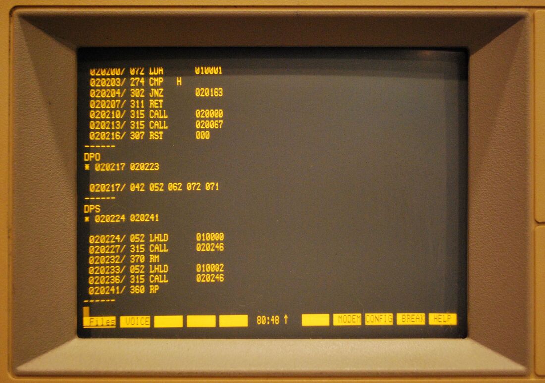
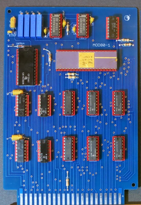
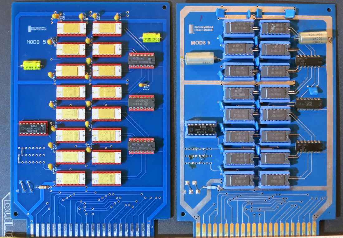
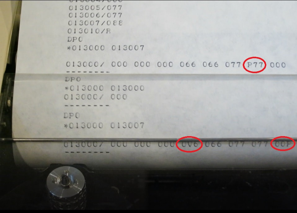
Borrowed some Monitor 80 EPROMs from a friend to compare against mine in an attempt to figure out what was different. It seemed that something was different in the last two EPROMs (at address 020000-021377) as when I used his EPROM card, it worked. However when I compared the ROM contents to mine, they were identical! So there must be something wrong with my ROM card.
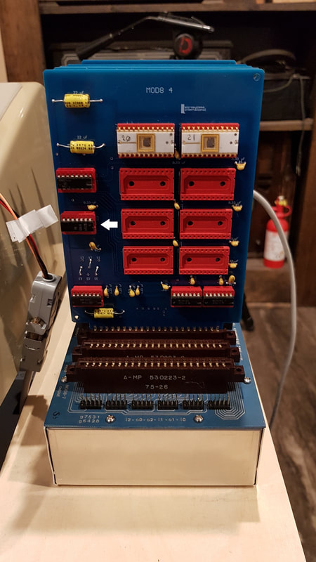
After testing the other chips on the card, I discovered that the 7400 chip wasn't fully functional. After that was replaced, my setup worked as it should.
After testing the other chips on the card, I discovered that the 7400 chip wasn't fully functional. After that was replaced, my setup worked as it should.


 RSS Feed
